Radio
Radio
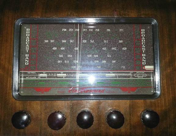
Electrosound Radio with SSB detector

This radio was made in Australia probably around 1950. It is a large receiver 560 x 380 x 295 mm in size, in a robust solidly built timber cabinet, with a powerful 8-inch speaker.
The radio has three bands:
- Broadcast medium wave band, 540...1650 kHz;
- Shortwave low "tropical" band, 2.5...7.5 MHz (120...40 m);
- Shortwave high band, 7.5...22 MHz (40...13 m).
Control knobs are (left to right): Tone, Volume/ON/OFF, BFO ON/OFF (AM/SSB), Tuning, Band switch.
It is a 7-valve radio with a unique feature -- beat frequency oscillator and a product detector for listening to Morse code (CW) or single side band (SSB) transmissions. Tube line-up is as follows: 6SK7 (RF), ECH35 (Local oscillator and mixer), 6SK7 (IF), 6SQ7 (AM detector, AGC detector, first audio stage), 6SA7 (Beat frequency oscillator and product detector), 6V6GT (Output audio), 5Y3GT (Rectifier). Circuit design is straightforward.
A quality triode-hexode ECH35 (red coated tube) is used which has high conversion transconductance (hence lower noise). It works with self-bias, and AGC voltage is not applied to it on shortwave bands, similarly to what described in another article. This improves frequency stability -- tuning or the radio does not drift or "swing" with the signal strength changing.
BFO and product detector schematic is shown below.
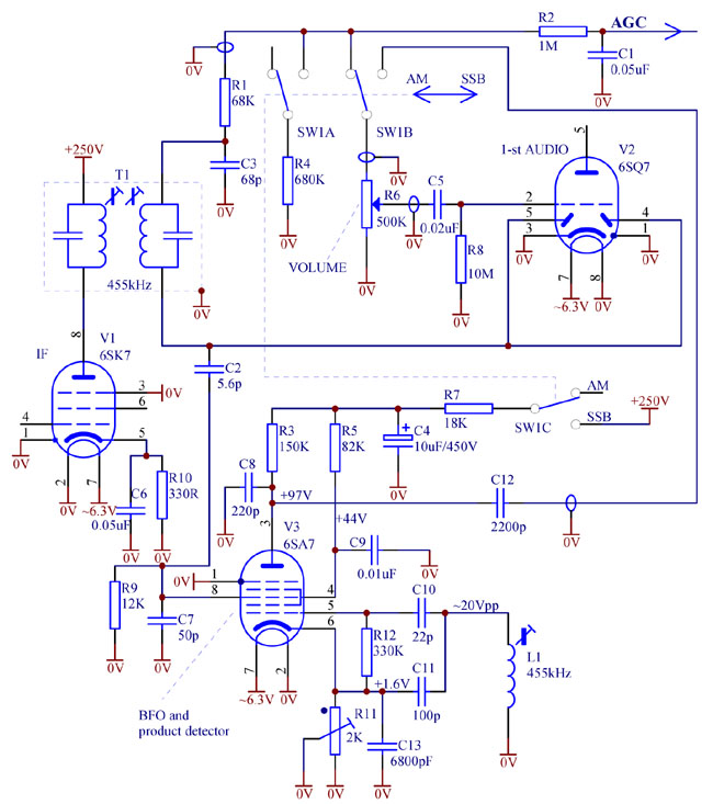
IF signal is fed to the product detector via C2. To avoid overloading and direct demodulation, the signal is attenuated by 20dB through capacitive divider C2C7. Relatively low value of R9 prevents audio components from the IF transformer T1 from directly entering and being amplified by pentagrid V3. Filter R7C4 removes ripple from the supply voltage thus eliminating hum in SSB mode. Relatively small value of interstage audio couplling C12 cuts low audio frequencies, and voice sounds better. Besides it helps prevent motorboating.
In AM mode, volume control potentiometer R6 serves as a load for the AM detector. In SSB mode, for correct operation of AGC, this load is substituted by R4.
Screen grids 2 and 4 of the pentagrid are not decoupled at audio frequencies. This increases the gain of the product detector. For example, suppose that at some point in time, signal grid 3 is out of phase with grid 1, and plate current tends to reduce. It means that screen grid current has to increase by the same amount because of redistribution of cathode current. However, since screen grids are not bypassed at audio frequencies, screen voltage lowers, which causes the cathode current to lower as well, further reducing plate current.
With its two shortwave bands, this radio covers amateur bands of 80m (3.5MHz), 40m (7MHz), 20m (14MHz) and even 15m (21MHz). On the low bands, 80m and 40m, ham operators use low side band, on the high bands -- upper side band. Because the local oscillator runs above the signal frequency, side bands get inverted at IF -- upper on low bands, lower -- on high bands.
Therefore, to obtain some suppression of an unwanted side band, it is better to tune the BFO (L1) to the low slope of the IF passband for 80 and 40m, and to the upper slope of IF passband for 20 and 15m. Given that tuning accuracy and stability may not be sufficient for 20 and 15m, it is recommended to use this receiver for casual listening on 40m and 80m and consequently to tune the BFO slug to the lower slope of IF passband. You can view a demonstration here.
If listening to both upper and lower sidebands is required, then as a matter of a tradeoff, the BFO can be tuned to the middle of the passband (to nominal 455kHz). In this case there will be no suppression of unwanted sidebands.
Trimmer R11 is used to minimise direct AM detection by the product detector. This phenomenon utilises S-shaped control characteristics of grid 3. R11 virtually changes negative bias on grid 3. It is known that with low negative bias, increase of IF signal at grid 3 would cause plate current to reduce, like in a grid-leak detector. If the negative bias is high, and the grid 3 is closer to cut-off, then increase of IF at grid 3 would result in the plate current rising, like in an anode bend detector. Obviously, at some bias value these two non-linearities cancel each other in the first order approximation.
Therefore to "balance" the product detector for the best sound quality, it is recommended to:
- tune into a strong station which would produce large IF voltage at grid 3 of the pentagrid V3;
- detune BFO (L1) away from the IF frequency to make the beat frequencies high and inaudible;
- adjust R11 to get the sound resulting from the direct demodulation as soft as possible, almost inaudible;
- then tune L1 back within the IF passband, slightly off centre, depending on which sideband is desired, as explained above.
Adjustment of R11 is not critical. It might be done after changing the 6SA7 valve. If several samples of 6SA7 are available, it is advised to choose the least microphonic one. In this respect metal 6SA7 are better than their glass siblings 6SA7GT.
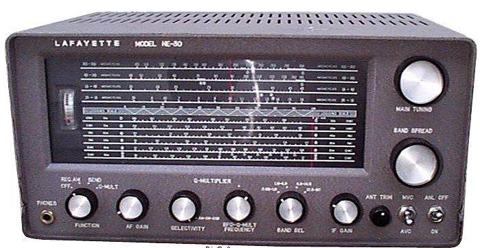
1. Drawbacks of the original design of Lafayette HE-30 / KT-320
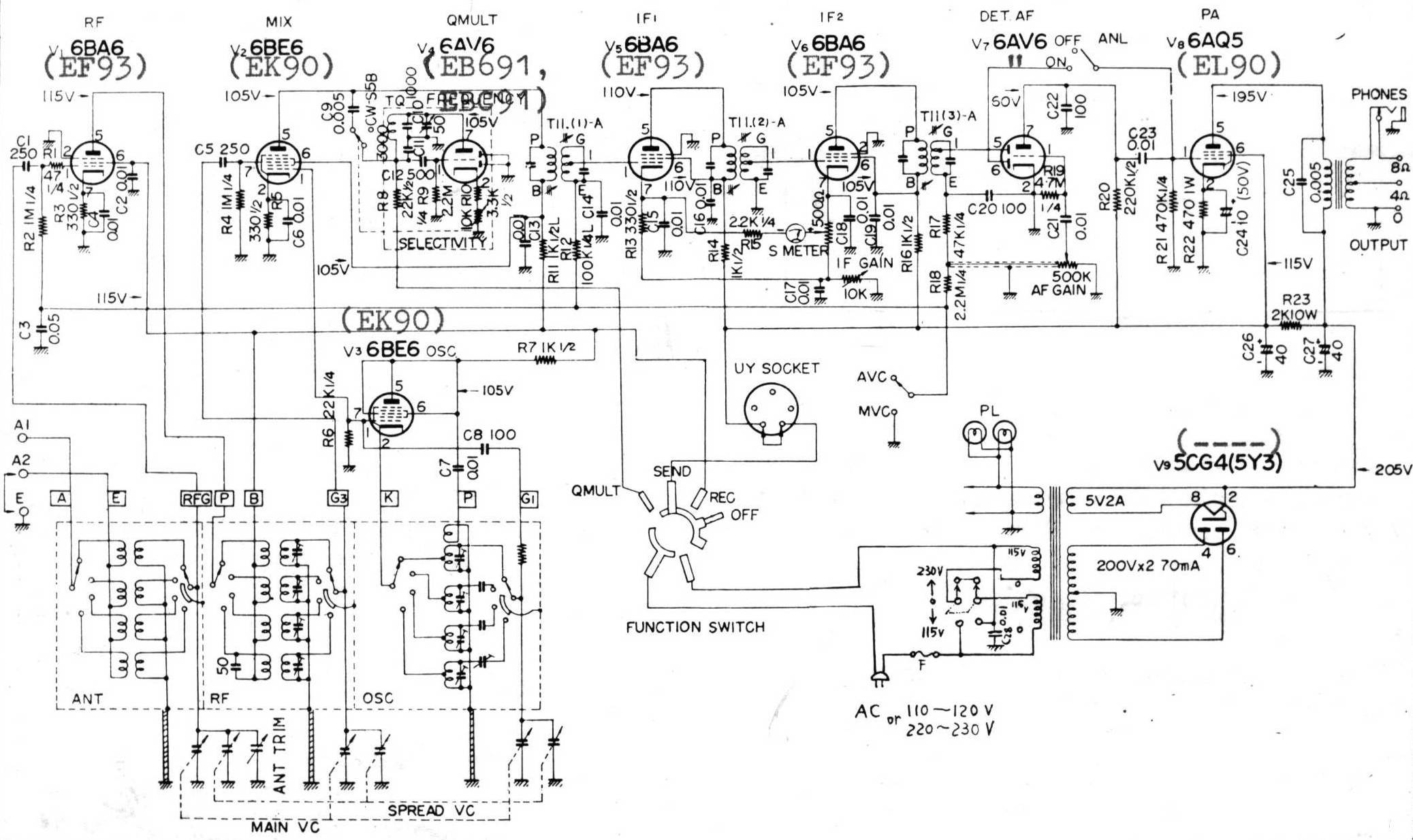
Lafayette HE-30 (similar to Trio 9R-59) and its kit version KT-320 is a basic single conversion tube semi-professional short wave communications receiver. More about this receiver can be found in another article.
As many other similar designs, it has one RF stage (6BA6), local oscillator (6BE6 in triode), mixer (6BE6), two IF stages (6BA6), AM detector and first audio (6AV6), output audio (6AQ5), rectifier (5CG4). This model also has a Q-multiplier (6AV6) which can work as a BFO if driven into continuous oscillation. BFO signal is injected into the 1-st IF input via stray coupling.
You can download original HE-30 schematic here.
You can download full HE-30 operating manual here.
Original HE-30 receiver has several drawbacks. To name a few, it has less than desired frequency stability at the top band, low audio quality, poor SSB reception and almost useless Q-multiplier.
Using the Q-multiplier for shortwave AM listening serves no purpose as the IF bandwidth of the radio is already quite narrow (4kHz).
In the SSB mode, the Q-multiplier is biased into self-oscillating mode and its signal is injected (through a stray capacitance) to the first IF transformer. As a result, a large AGC voltage is developed on the AM detector which desensitizes the receiver. (One can use manual gain control though.)
Another problem is when one attempts to place the BFO frequency on a slope of the IF curve to get a true SSB reception, the BFO signal gets attenuated, because the IF gain is smaller on the slope. Thus the BFO signal becomes insufficient and strong interference may drown a signal of interest by crude direct AM detection. Attempts to reduce RF gain do not help, as this also reduces the IF gain and makes the BFO level even smaller.
The above drawbacks make the HE-30 / KT-320 receiver very inconvenient for SSB listening.
2. Product SSB detector
To overcome the above mentioned deficiencies of an injected BFO approach, in the later models a dedicated SSB product detector using a heptode (pentagrid) appeared. A representative example is Trio/Kenwood 9R-59DS receiver.
You can download original 9R-59DS schematic here.
You can download full 9R-59DS operating manual here.
Below is a fragment of the 9R-59DS circuit of the product detector.
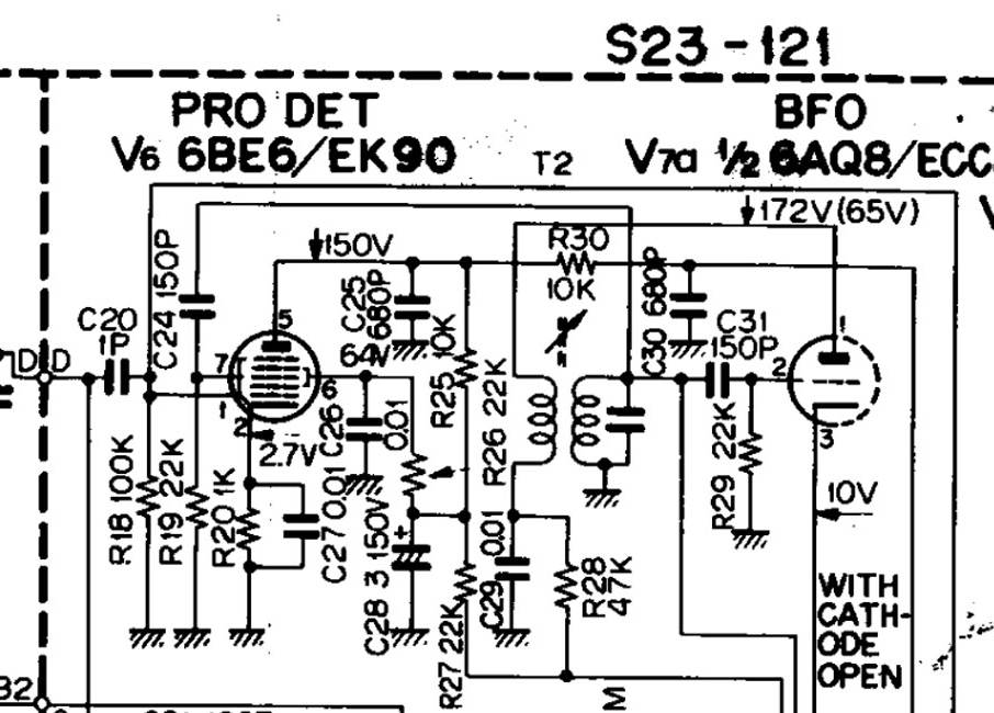
Fig. 1. Product SSB detector in 9R-59DS receiver.
It uses a heptode (pentagrid) V6 6BE6 and a separate BFO oscillator. It might be tempting to fit a similar circuit in HE-30, but such direct "copy-and-paste" is not practical for the following reasons:
a) These are no spare tube sockets in HE-30 to add the product mixer and the BFO;
b) There is no spare wafer on the mode switch to switch audio path from either AM detector or the SSB detector to volume control;
c) The IF signal is fed to the first grid of the heptode (pentagrid), and the BFO -- to the third grid. Because of the space-charge coupling, the BFO might be pulled by strong signals. This is particularly noticeable when listening to strong AM stations in SSB mode. Close to zero beats the sound becomes coarse and unpleasant.
Therefore, a different solution is needed for implementing a product SSB detector in HE-30.
2. Fitting a product SSB detector into a HE-30 receiver
A schematic diagram of the modifications required to add a product SSB detector to HE-30 / KT-320 receiver is shown in the picture below.
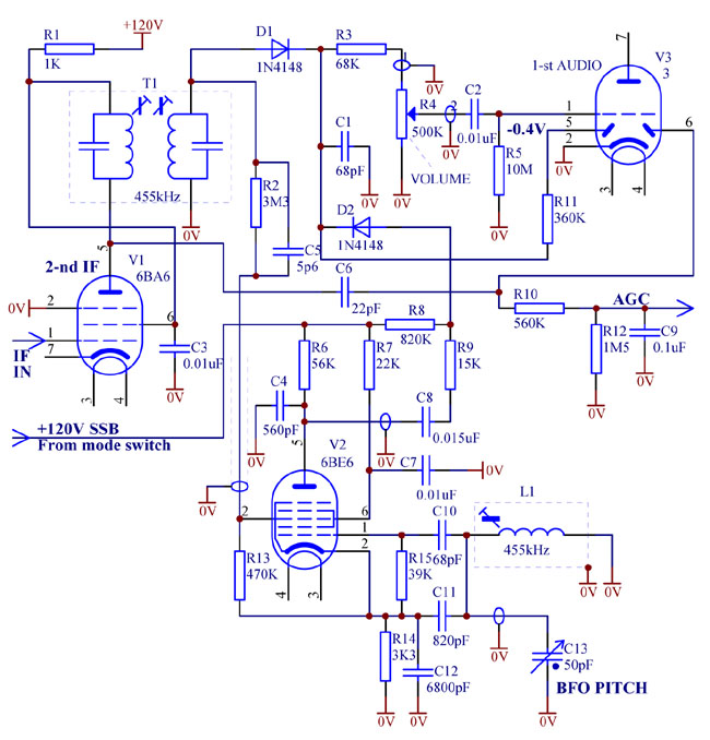
Fig. 2. Product SSB detector in HE-30 receiver.
Let us discuss the main features of the circuit.
a) Separate AM detector and AGC detector.
In the original HE-30, AGC is derived from the main AM detector. Thus the AM detector gets "AC burdened" by the AGC filter and can not handle more than 70% modulation. In the proposed circuit, the detectors are separate which allows the main AM detector to handle deep modulation.
b) Forward bias of the AM detector diode.
As can be seen, a silicon diode D1 is used in the AM detector. An unusual feature is that the diode is lightly forward biased to the "kink" by a negative voltage generated by thermionic electron emission in one of the diodes of V3, 6AV6. Forward vias voltage is about 0.3V. It is a custom belief that the "kink" of a silicon diode is 0.6..0.7V. However, at minuscule nanoampere range currents conduction actually begins at low voltages, 0.25...0.4V, especially when the radio is warmed up. Thus the 0.3V bias is near optimum and the small-signal sensitivity becomes better than of a vacuum diode. The detector works directly into the volume control and not burdened by parallel loads. Resistor R3 together with capacitance of the shielded cable filters the IF residual ripple.
c) Heptode (pentagrid) product SSB detector.
Here the heptode V2 works with the oscillator voltage applied to grid 1, and the IF signal -- to grid 3. Such topology is much better in terms of reducing parasitic coupling between the IF and BFO. In a heptode 6BE6, backward space-charge coupling from grid 3 to grid 1 is almost non-existent, thus the BFO is not synchronised (pulled) by the IF signal. (As a side note, old pentagrids 6A7 and 6A8 are much worse than 6BE6 and 6SA7 in this respect and have notoriously bad space-charge coupling in both directions.)
The circuit uses capacitive coupling to the BFO LC tank, as opposed to inductive coupling commonly found in frequency changers of the radios. IF signal is applied to grid 3, through a capacitive divider comprising C5 and the shielded cable capacitance. The divider reduces the IF AC signal on grid 3 to under 100mV to avoid overloading and distortion. Also it helps make the overall gain of the product detector about unity -- so that volume of the radio does not change much when switching from AM to SSB mode. Resistive divider R13R2 produces optimum negative bias on grid 3 with respect to cathode to set the grid 3 operation point to the linear region and minimise quadratic direct AM rectification.
Note that C7 is relatively small, and screen grids 2 and 4 are coupled to ground at IF, but not at audio frequencies. This trick actually increases the effective conversion transconductance. Why it is so -- let the reader find out. C4 filters out residual BFO and IF ripple.
d) Electronic switching between AM and SSB modes.
As was mentioned earlier, HE-30 does not offer a spare wafer on the mode switch to be used in the audio path. So switching into SSB mode is done by applying "+120V SSB" from power supply rail of the receiver.
In AM mode, this voltage "+120V SSB" is disconnected and floating. Heptode V2 is dormant. Thermionic electron emission in V2 charges grids 2, 4 and the plate slightly negatively, which, through R8, reverse biases the switching diode D2, and the product detector gets virtually completely decoupled from the AM detector (which develops positive voltage further reverse biasing D2).
To switch to SSB mode, +120V DC or so is connected to "+120V SSB" line. Heptode V2 powers up and starts to oscillate. Product detector comes to life. At the same time, current through R8 forward biases D2, which dynamic resistance drops to a hundred ohms, effectively connecting the product detector to the volume control through C8R9. At the same time, this current creates about +40V DC on R3, R4, reliably reverse biasing the AM detector diode D1, even for the strongest signals. Thus the AM detector gets completely disabled, and SSB detector enabled.
A drawback of such electronic switching is a possibility of crackling when turning the volume control rapidly, because there exists a large DC voltage across it. However it is non issue if the volume control potentiometer is clean and not worn out. On the other hand, electronic diode switching has an advantage that there is no risk of intermittent contact, which may occur if low level, high impedance audio signals are switched conventionally by mechanical switches, if the later get oxidated.
Components V2, R6, R7, R13, R14, R15, C4, C7, C10, C11, C12 should be mounted in the same metal compartment where originally the Q-multiplier used to reside. C10, C11 and C12 must be mica or NPO (COG) temperature stable capacitors. Other components can be mounted closer to the third IF transformer and 6AV6 tube socket. The cables shown shielded, must be shielded. R2, C5 should have short leads.
Pentagrids 6BE6 were not generally designed for audio applications, and some, especially old cheap mass-produced tubes can be microphonic. Tube selection on test may be needed.
It is recommended also to regulate supply voltage to the local oscillator and the BFO, as described here.
Similar approach to adding a product SSB detector may apply to older communication receivers with octal valves. In this case, the mixer tubes with the first grid as oscillator grid should be used, like pentagrid 6SA7 or triode-hexode 6K8. Old 6A8 shall be avoided as it suffers badly from space-charge coupling.
Radio
Collecting of old vintage tube radios is fun. Some people use them as display items, others meticulously restore them to original specifications, yet others make modifications so that the radios can be used safely and enjoyed. Performance of vintage radios is quite poor according to modern standards -- poor frequency stability, narrow audio bandwidth, high audio distortion, noise and hum.
Collection of articles in this section might help the restorers to improve performance to make their vintage radios more usable and listenable.
1. Original design
Lafayette HE-30 (similar to Trio 9R-59) is a basic single conversion tube semi-professional short wave communications receiver. It covers 0.55 to 30 MHz in four bands. It has bandspread function by way of a small variable capacitor connected to each gang of the maim tuning variable capacitor.
As many other similar designs, it has one RF stage (6BA6), local oscillator (6BE6 in triode), mixer (6BE6), two IF stages (6BA6), AM detector and first audio (6AV6), output audio (6AQ5), rectifier (5CG4). This model also has a Q-multiplier (6AV6) which can work as a BFO if driven into continuous oscillation. BFO signal is injected into the 1-st IF input via stray coupling.
You can download original HE-30 schematic here.
You can download full HE-30 operating manual here.
Original HE-30 receiver has several drawbacks. To name a few, it has less than desired frequency stability at the top band, low audio quality, and almost useless Q-multiplier. Some simple modifications, described below, can greatly improve performance of this vintage radio.
2. Voltage regulator
In the original design all the LO, mixer, IF stages, Q-multiplier and even the screen of the output audio stage are powered by an unregulated voltage about 110...140V. Needless to say, local oscillator frequency depends on the mains voltage -- frequency sometimes jumps with turning on of an air conditioner or a microwave oven in the household. Sometimes signal strength affects the LO frequency. Automatic gain control changes current draw of the RF anf IF stages, which causes LO supply voltage to change -- hence frequency drifts. Besides, unregulated voltage supply to the IF counteracts AGC operation.
Adding a voltage regulator for the RF, LO and IF stages solves the above problems. An example of such a regulator is shown below.
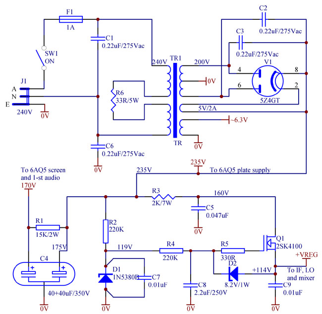
Regulated voltage of about 114V is close to optimum. A Zener diode is used as a reference. A high transconductance Q1 MOSFET 2SK4100 provides good load regulation. Suppressor resistor R5 is essential. It shall be connected directly to the gate pin of Q1. Another Zener D2 is for the MOSFET protection. R4C8 filters Zener noise and ripple.
High voltage Zener diodes are very noisy in the wide frequency band. For that reason, to filter RF component of the noise it is very important to connect a shunting low inductance disk ceramic capacitor C7 as close as practical to the Zener body and on the shortest leads, for example, as shown in the picture below.
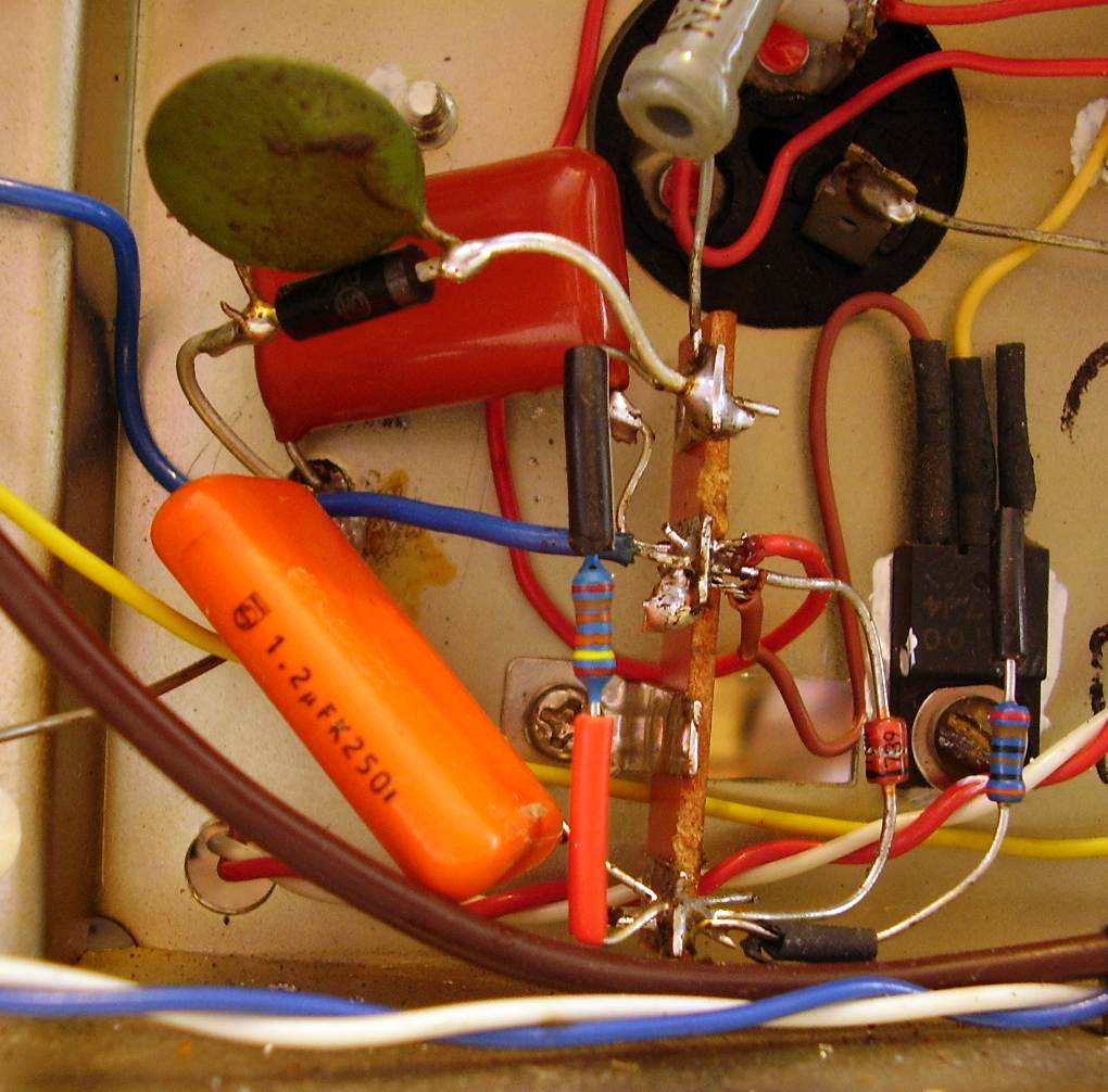
It is also advisable to mount the Zener D1 away from the sensitive RF or IF nodes, to avoid the residual noise leakage into the receiver signal or IF path. In the given example the regulator is located in the corner of the chassis near the phones connector -- far away from any RF circuity. It is very convenient to choose Q1 MOSFET in a fully insulated TO-220F package and mount it directly to the chassis for a heat sink.
Now when the HF stages get regulated supply, the other section of the C4 electrolytic capacitor can be used solely for filtering of the supply to the AF amplifier: the first stage (6AV6) and the screen grid of the output stage (6AQ5) . Filtering resistor R1 can now be larger, giving an excellent hum reduction. Besides a higher voltage (175V as compared to the original 110V) is available on the 6AQ5 screen grid, which increases audio output power.
It is also recommended to replace the original 5CG4 rectifier with a 5Z4GT, which has a lower voltage drop, or even with the silicon diodes 1N4007. C1, C2, C3, C6 are optional to reduce the modulation hum (tuned hum), but with the vacuum rectifier it is virtually non-existent anyway. An optional dropping resistor R6 may be used if the mains voltage is consistently higher than nominal, like say in Australia, where it is usually 240...250Vac most of the time.
3. AM detector
In the original HE-30 design the AM detector is AC loaded by the AGC filter R18C3. It limits the maximum undistorted modulation handled to about 75%, while nowadays MW and SW broadcast stations use up to 100% modulation. A relatively large loading capacitor C20 (100pF) further contributes to distortion at higher AF frequencies.
To improve audio quality it is recommended to:
- separate AGC detector and audio AM detector;
- reduce capacitive loading on the AM detector;
- use a sensitive Schottky diode instead of a vacuum detector (6AV6).
A picture below illustrates these changes.
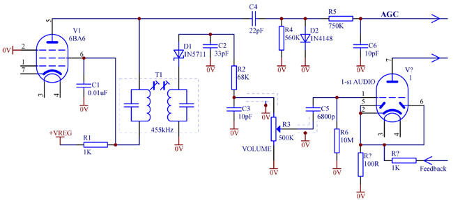
A 1N5711 Schottky diode in fact has so small "knee" (about 50mV at those sub-microamp currents) that it works better than a vacuum diode at low IF levels. Its low capacitance (1.5pF) helps reduce IF losses in C2. Capacitor C3 may be omitted, as the capacitance of the shielded cable to the volume control potentiometer gives enough filtering. A small "knee" of about 0.5V of the AGC detector silicon diode D2 provides a mildly "delayed" AGC action. Total grid leakage R4+R5 resistance is lower than the original 2.2M, which makes the circuit more forgiving to old and gassy tubes. Besides, now the diodes in 6AV6 are no longer used, hence the cathode of 6AV6 can be lifted of the ground and can be used for a negative feedback from the secondary winding of the output audio transformer.
4. Q-multiplier / notch filter
A Q-multiplier, which was intended originally to pull weak ham AM signals, in modern days is almost useless. It narrows down the bandwidth, making the sound of the AM stations even more "low" and muffled. Besides a Q-multiplier working close to the oscillation point is prone to distortion, "ringing" and instability.
To reduce interference, it is far better to suppress an interfering signal, rather than peak on the signal of interest.
AM detector is fundamentally a non-linear device. If two signals are present at its input, on the output there will be not a sum of both demodulated envelopes. Instead, a stronger signal suppresses a weaker one. Suppose the weaker one is the interfering signal. It will turn into a "whistle" or a "monkey-chatter". At the same time, the weaker interference signal becomes a "floor" for negative modulation excursions of the signal of interest. Thus an interference does not only add to the signal of interest as a "whistle", but it also limits and distorts the main signal. For that reason such interference can not be simply removed at audio frequencies by a treble tone control or an audio notch filter. Such technique might reduce the "whistle" but will not eliminate distortion and partial loss of the signal of interest.
It is more useful to try to remove the interference in front of an AM detector. A narrow-band notch filter can be used for such purpose.
Converting a HE-30 original Q-multiplier into a notch filter is easy -- one has to couple a Q-multiplier to an IF tank not in parallel, but through a small (15...22pF) series capacitor. In this case, a sharply tuned Q-multiplier LC tank at its resonant frequency will start to "suck" energy from the IF path, creating a notch.
An implementation of such a notch filter is shown below.
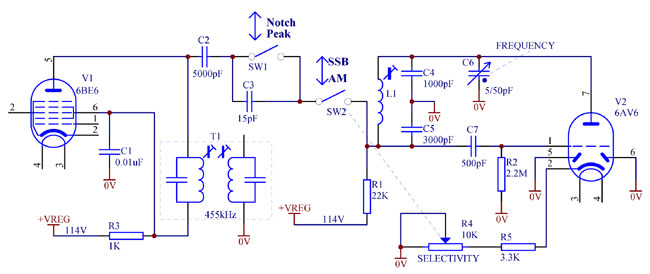
Original circuit, mounted in an enclosed metal compartment, does not change. Connection to the IF transformer changes. To switch between the normal peaking mode and new notch mode, a former noise limiter ON/OFF switch (SW1) can be used. When C3 is bypassed, the Q-multiplier works in the normal peaking mode, when C3 is in circuit -- in the notch mode.
5. Eliminating RF stage parasitic self-oscillation / instability
Sometimes RF amplifier in Lafayette HE-30 communication receiver becomes unstable and self-oscillates. Such parasitic oscillation usually manifests itself when adjusting the "Antenna trim" control, touching antenna connector or attempting to tune slugs and trimmer capacitors of the RF stage. Its symptoms are abrupt, intermittent and inconsistent abnormal noise level jumps, suspiciously sharp peaking of antenna trimming, crackling, whining, buzzing, hum, excessive microphonics, loss of reception, etc.
Usually such oscillation occurs in the middle of band 4 -- between 12 and 20MHz -- when antenna cable is unplugged and thus the antenna input LC tank Q is not damped by antenna impedance and with IF/RF gain control set to maximum. Band 3 also can be affected by this "disease", but not that often as band 4.
The cause of such problem is not apparent. Improving cathode and plate circuit bypassing and decoupling of the 6BA6 based RF stage does not help (though shortening the leads of 0.01uF disc ceramic decoupling capacitors helps marginally), so it is not a circuit design issue.
Additional shielding and separation of 6BA6 grid and plate circuitry, replacement of the tube does not change anything, so it is not stray or interelectrode capacitance to blame.
Extending aluminium coil separation partitions, inserting additional bridging metal plates to isolate, enclose and magnetically shield the coils has no effect. So magnetic coupling of the RF and antenna coils is not the root of the problem either.
Reducing RF gain, for example, by fitting a remote cut-off pentode with lower transconductance, such as 6К1П (or 9003, 6K1P), provided the socket is rewired to connect pins 2 an 7, can cure the oscillation problem, but sensitivity of the already noisy receiver suffers. The same "cure" can be achieved simply by fitting a larger (470...1000 Ohm) self-bias resistor in the cathode of RF amplifier.
So all the above tests lead to conclusion that some obscure evasive coupling between input and output of the RF stage does take place and causes the instability, but where exactly is this parasitic feedback path?
Cause of the problem
Further investigation and analysis shows that the spurious coupling between the RF stage plate LC tank and grid antenna tank happens through the common parasitic grounding impedance of the shaft, sliding contacts and grounding braided straps of the gang tuning capacitor. Due to this impedance, the shaft (rotor) appears not fully earthed. RF current circulating in the plate RF LC tank induces some voltage on the rotor assembly, which voltage consequently gets injected into the antenna tank. Further there is a reason to believe, that ohmic resistance of the rotor grounding, rather than shaft inductance, contribute to the said impedance.
As a receiver gets older, earthing sliding contacts in the triple-gang capacitor wear out, get dirtier and lose tension, which results in the contact resistance increase. Braided earthing straps (and possibly mounting screws) get oxidated, tarnished or surface-corroded, which, due to skin effect, also increases the grounding impedance at higher frequencies. As a result, older Lafayette HE-30 receivers, and possibly others, like Trio 9R-59DS, are more likely to suffer from this RF oscillation syndrome. By the way, all three LC tanks on the shaft of the triple-gang capacitor get coupled, which explains why local oscillator frequency is sometimes affected by the "Antenna trim" control.
Cure
The easiest practical treatment is to arrange an external coupling between the plate and grid tanks, equal in magnitude, but opposite in phase to the offending spurious coupling. The following pictures illustrate the technique.
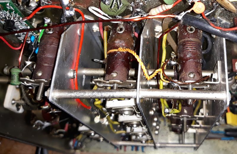
External loop coupling is introduced between RF and antenna LC tanks. One turn is placed on the former of the RF coil, twisted "feeder" runs into antenna coil compartment, loose turn of enamelled wire is created around the antenna coil. Polarity and magnitude of the coupling is determined empirically. Coupling strength is adjusted by moving the loops closer or further away from the coils. However it is more practical to fix one of the loops (on the RF tank in this case) in place by wax, make the other loop flexible and "massage" it to achieve a desired level of coupling. The "feeder" between the loops is the same insulated wire (yellow in the photos) from which the first loop is made -- closely twisted to reduce leakage inductance of the "feeder".
The next picture illustrates how the secondary loose loop around the antenna coil is made from 1mm enamelled copper wire and soldered between a lug on the coil former and the metal mounting bracket.
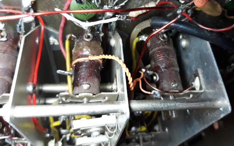
Secondary loop is loose and made of 1mm copper enamel wire to be flexible. Making the loop larger and bending it further away from the coil reduces the coupling, and vice versa.
In the next close-up, the secondary loop does not look like a circular loop at all. It is distorted, flattened and bent away from the antenna coil winding.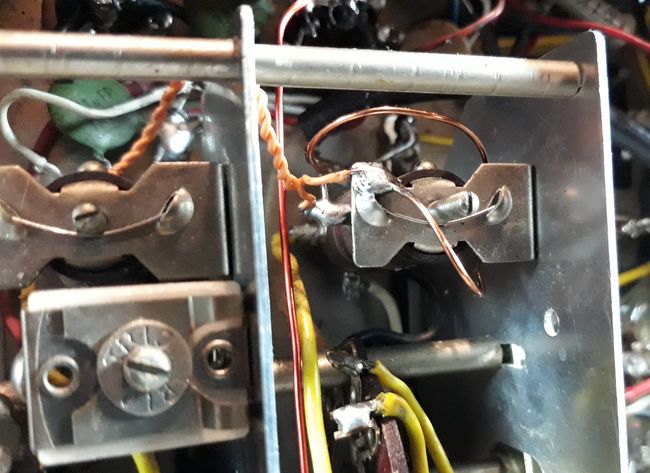
That was done apparently in attempt to reduce coupling to some optimum level. Alternatively, to get a neater look, both loops can be made like the primary one -- as a single tight turn. Then coupling factor can be adjusted by sliding the loops along both coil formers. It may become problematic, as the lugs on the coil formers are in the way. Yet another coupling control method is inserting a variable inductor in series with the loop. This may not be practical too, as it requires to have assorted inductors in 0.5...5uH range at hand.
Adjustment procedure
1) Note that frequency range where the parasitic oscillation is the most "violent", that is occurs at the lowest IF/RF gain control setting of the radio.
2) Make the primary loop with a twisted "feeder" from a single-strand insulated wire and fix it on the RF coil former with wax, as shown in the photos above.
3) By relocating 100pF grid decoupling capacitor, free the solder lug on the antenna coil former. Tin the corner of the coil mounting bracket and solder the "feeder" to these two respective anchor points.
4) Prepare a secondary loop from approximately 0.8...1.3mm enamelled copper wire. Too thin will be flimsy, too thick -- too stiff to bend. Solder this secondary loop between the bracket and the lug.
5) Remove (pull out from socket) the RF stage 6BA6 tube, tune the radio to the "worst case" frequency, determined at step (1) and apply some strong signal at this frequency to the antenna input, so that you can actually receive this signal without the RF stage only through the parasitic coupling between antenna and RF coils. For example, a fluoro table lamp with antenna wire loosely wrapped around the fluoro globe will be a perfect source of strong wide-band noise. An brushed electric motor, for instance in a shaver can do the job too.
6) Now the aim is to "massage" the secondary loop in such a way to minimise leakage of that noise -- to make the noise sound as quiet as possible. First of all, polarity or direction of the secondary loop connection shall be established so that it actually reduces (cancels) the noise, not increases it. If the loop makes the noise only stronger, its polarity should be reversed. Then the loop should be gently moved and/or bent spatially to find a position where the noise leakage reaches the minimum. Use some dielectric implement to bend the loop. This minimum should be quite distinct, like tuning a notch filter. The loop should be left in the position of the best cancellation or in slightly under-compensated position, but not over-compensated.
Once the above adjustment is complete, RF stage tube can be plugged back in, and hopefully the receiver will rid of the oscillation problem. However, in some severe cases, after the above treatment the RF instability might start manifesting at some other frequency, typically higher. This is because such compensation, unfortunately, is frequency dependent and does not cover all the band. It works well only around a certain frequency. Therefore, if after this treatment parasitic oscillation will reappear at some other frequency, the procedure shall be repeated -- at a frequency somewhere between the original worst case and a new problematic point. Second iteration is quite easy as the loops are already installed, and only a little more bending will be needed.
Converter frequency stability
Many of the old valve radios have shortwave band(s). Usually the first stage is a frequency converter using a multigrid tube: heptode, pentagrid, triode-hexode, triode-heptode, octode, etc. Those tubes are noisy -- equivalent noise resistance referred to the signal grid is 50...150KOhm, which limits sensitivity on short wave bands, when the impedance of the RF signal LC tank becomes lower than the equivalent noise resistance of the converter.
Another common problem -- low frequency stability. Not only frequency drifts with changes of temperature, supply voltage and heater voltage, but also with changing automatic gain control (AGC) voltage. On high frequency bands (13, 16 and 19m) this drift can become so pronounced (more than 5KHz) that on a fading shortwave station a receiver would be tuning in and out of the station, which degrades reception quality.
The worst converter tube in this respect is 6A7 or 6A8. A typical generic front end converter circuit is shown in Fig.1.
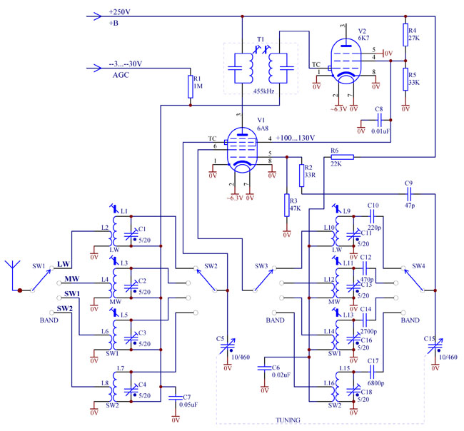
Fig. 1. Typical frequency converter using pentagrid 6A8.
In this tube, 6A8, local oscillator (LO) runs on a virtual triode, grid 2 (actually two metal rods) being its plate. When negative AGC voltage increases, reducing conversion transconductance, signal grid 4 starts repelling more electrons, sending them back -- towards screen grid 3. However, many of these returning electrons are not intercepted by grid 3, but travel further towards cathode to positively charged rods of grid 2 (oscillator plate). Some of these electrons got caught by the rods, thus increasing oscillator plate current.
Therefore, in 6A8 increasing AGC causes rise of the oscillator transconductance, which inevitably affects frequency. Also, since the returned electrons come to grid 2 with a longer delay than those which arrive straight from the cathode, this propagation delay pulls the frequency down. Some electrons manage to make several trips back to negative grid 1 and forth to grid 4, until caught by some positive grid on the way. Such unprofitable "traffic" contributes to so called space charge build up near negative grids -- above grid 1 and under grid 4. Such space charge adds to frequency instability and causes parasitic coupling between the LO and signal LC tanks.
To improve frequency stability it is possible to use more advanced frequency changer tubes (triode-hexodes) with separate electron flow for oscillator and mixer sections. Such tubes are 6J8, 6K8, though they have smaller conversion transconductance (250...350uA/V), and the European series, for example ECH3, ECH35, ECH80 (6AN7A), ECH81. The later have high transconductance (600...750uA/V) and acceptable stability for AM listening.
For a demanding listener and for SSB applications this can be still insufficient. To further improve performance, three modifications are needed:
1) Not using AGC in the converter stage on short waves;
2) Regulation of screen grid and LO supply voltage;
3) Separating screen grid supply filters to prevent AGC operation in the IF stage affecting screen voltage in the mixer;
These simple modifications are shown in Fig. 2 below.
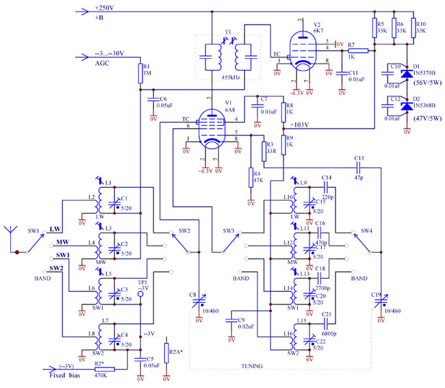
Fig. 2. Frequency converter with improved stability and fixed bias.
As can be seen from Fig. 2, the "cold" ends of the signal LC tanks are separated. On long and medium wave bands the mixer receives AGC via R1C6 filter, while on short waves fixed bias voltage is supplied through R2C5. Bias voltage must be free of ripple and preferably regulated. It can be taken from a bias resistor or a suitable Zener diode inserted in the "negative" leg of the power supply circuit, or from a dedicated regulated supply. Voltage should match recommended specification for a tube. For example, 6A8, 6K8 or 6K8 would need --3V, while ECH35, 6AN7A (ECH80), ECH81: --2V. Divider R2R2A can be used to obtain the desired bias voltage.
Supply voltage regulator Zeners D1 and D2 require special attention. Firstly, it is better to use two Zeners with total 100...105V voltage, rather than only one. It helps share power dissipation and have them running cooler. Secondly, Zeners are notorious for generating wide-band noise. To prevent it from propagating through the circuit and being picked up by sensitive stages of the receiver, each Zener shall be shunted by a low-inductance (e.g., disk ceramic) capacitor, soldered as close as practical to the Zener body. Capacitor's leads shall be kept as short as practical too. These measures reduce the "loop" inductance and help minimise radiation of magnetic noise, as well as minimising noise voltage across each of the Zeners.
Using one shunt capacitor for both Zeners is not acceptable, as the "loop" area will be significantly larger. Also do not attempt specifically to solder the filtering capacitors to chassis, but solder to the Zener's leads close to its body. Even after all the precautions are taken, it is better to place the Zeners in the power supply "section" of the chassis and away from the sensitive nodes -- RF input, antenna circuit, first IF grid.
An example of Zener bypassing by a disk ceramic capacitor is shown in a photo below.
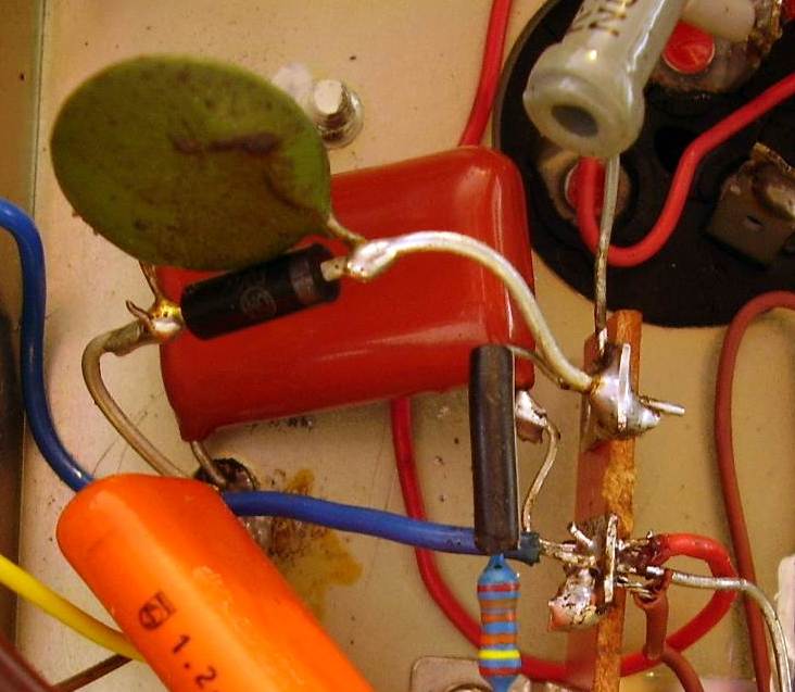
Fig. 3. Shunting a high voltage Zener by a disk ceramic capacitor.
Instead of fixed bias on the short waves, self bias (automatic bias) can be used, especially in the later models of vintage radios from the 50's. Self bias does not require a regulated negative voltage. The circuit can become simpler. An example of such circuit is shown below.
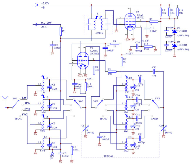
Fig. 4. Mixer with self bias.
In this case, AGC voltage starts from zero, not from --3V (or --2V) as in Fig. 1 or Fig. 2. For that reason, the IF stage also has self bias arrangement. Mixer triode-hexode tube 6AN7A (ECH80) is shown as an example, but any other will work too with appropriately chosen self bias resistor R11, for example, more popular ECH81.
Note that though DC potential of the RF LC tanks for the shortwave bands is zero, they are not directly grounded to chassis, but through a R2C5 filter. Such arrangement has several advantages explained below.
As commonly known, almost always there exists some parasitic coupling between the local oscillator LC tank and the RF LC tank. This coupling occurs through stray coupling between the coils, wiring and by the space charge within the mixer tube. If the outer grid is a signal grid (6A8, 6SA7, 6K8, EK2, EK3, etc.) it might be possible to compensate the coupling by a small capacitor, about 0.3pF, between the signal grid and oscillator grid of the mixer tube. However, if this coupling remains not fully compensated, then at high frequencies it causes a significant voltage to develop across the RF LC tank. If amplitude of this voltage exceeds the bias voltage, grid current in the signal grid 1 will start to flow. In this case input impedance of the signal grid will drop, the RF tank will get shunted, causing degradation of sensitivity and image rejection of the receiver and noise increasing. To avoid this effect, R2 is inserted. If a minuscule grid current occurs, it will develop additional negative voltage on the grid which might affect conversion transconductance, but will not degrade Q-factor of the RF tank and image rejection of the radio.
Test point TP1 can be used to monitor this grid current condition. If a multimeter connected to TP1 registers significant negative voltage (more than --0.5V), it means parasitic voltage induced on the RF tank is too high. It usually happens near the high frequency end of the dial.
To remedy this problem one might try to reduce local oscillator amplitude, adjust the small compensation capacitor mentioned above, attempt to put another compensation capacitor between the signal grid of hexode and the oscillator triode plate, swap the ends of the RF coil, install shielding between oscillator and RF coils, improve wiring, etc.
Oscillator stability of a receiver with RF stage
Simple single conversion "communications" receivers with an RF stage usually do not have AGC applied to the mixer. After the local oscillator (LO) and mixer screen grid supply voltages are regulated, oscillator frequency may still be affected by AGC operation, manual "RF/IF gain" control or even by "Antenna trim" adjustment. This effect is more pronounced on high bands. Why does it happen?
The answer is -- local oscillator injection into the mixer via signal path. At high frequencies, due to limited RF selectivity, local oscillator signal, if it leaks into the RF input, is not sufficiently suppressed. Thus it gets amplified by the RF stage together with the signal and gets injected into the mixer via signal grid. Then, through stray coupling or space-charge coupling between the signal and oscillator grids, it gets injected back into the local oscillator tank. Depending on the phase and amplitude of such back-injected signal, it pulls the oscillator frequency one way or another.
When AGC is working (or manual RF gain control is manipulated), RF stage gain is changing, back-injection strength is changing and consequently the amount of frequency pull is changing. Even turning "Antenna trim" capacitor changes the phase of the re-injected signal and affects the frequency pull. Thus the oscillator frequency drifts, which is annoying at least or unacceptable for a synchronous detector operation at worst.
How to remedy this phenomenon? Removing AGC from the RF stage on high bands is not recommended as it may result in overloading of the radio on strong stations. Better is to try to reduce back injection as much as possible.
Firstly, the shaft, sliding contacts and grounding straps of the multi-gang tuning capacitor shall be clean, corrosion free and well soldered. This will reduce LO leakage into the RF stage via common grounding impedance of the gang capacitor.
Secondly, RF input circuits shall be well clear of the LO circuitry. In some receivers, for example Trio/Kenwood 9R-59DS, a wire to the "Antenna trim" capacitor runs under the chassis close to the local oscillator components. Thus LO leaks into the antenna input circuit. Using a piece of a screened (coaxial) cable for that connection is not acceptable due to extra capacitance of the shielded cable. Better to run a flying wire above the chassis as shown in Fig. 5. It runs from the lug of "Bandspread" gang capacitor to the antenna trimmer under the chassis. The chassis and a shield on the oscillator tube ECC85 (left) reliably screen this connecting wire from LO radiation.
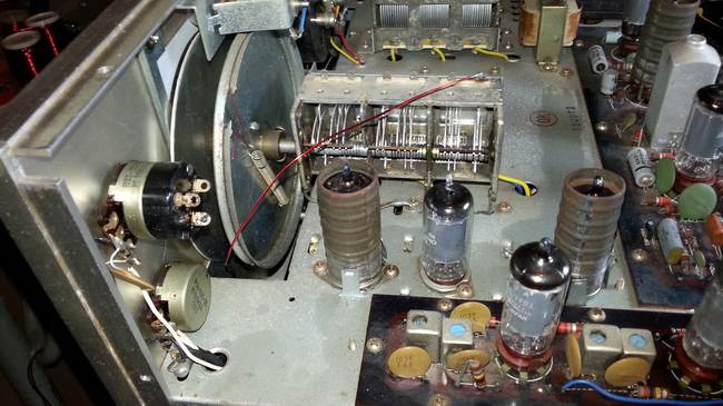
Fig. 5. Flying wire connection of the "Antenna trim" capacitor to RF antenna tank in Trio 9R-59DS receiver.