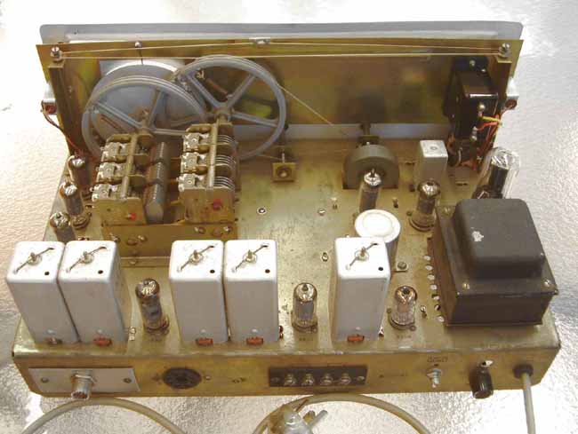
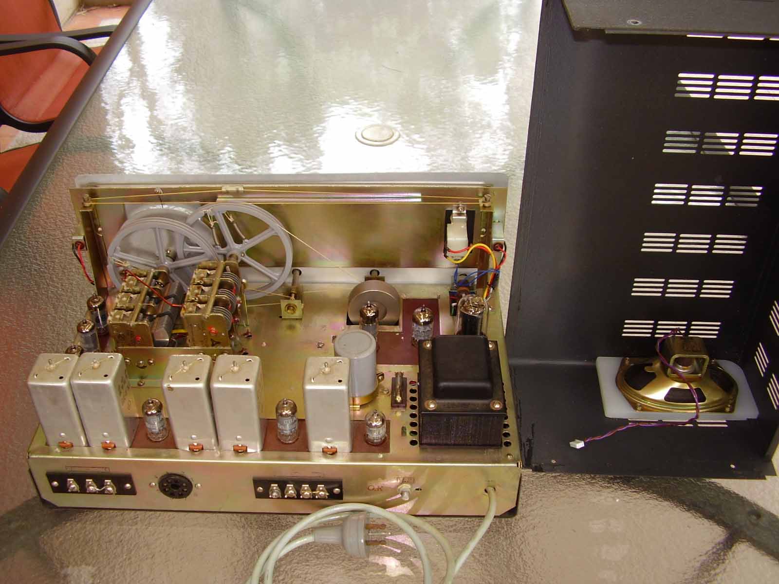
Tube communications receiver HCR-62 made by E.I.L. (Japan) is a single conversion superheterodyne. As many other similar radios, like Lafayette HE-30 and others, it has one RF stage, heptode mixer with a separate local oscillator, two IF stages, two AF stages, BFO and a rectifier. It covers 0.55MHz to 30MHz in four bands. It has a bandspread by means of a small value triple-gang variable capacitor, connected in parallel to the main tuning gang capacitor. The radio has a switchable AGC and automatic noise limiter, which does very little apart from distorting audio.
A unique feature of this receiver is five IF 455kHz transformers, which give a fantastic selectivity. It can rival a mechanical filter. However, IF bandpass is far from square shaped. It is rather bell shaped, which leaves too narrow bandwidth for AM reception. This radio has no antenna trim capacitor, but sensitivity and image rejection seem sufficient on all the bands. Unlike in other receivers of this class, the BFO is tuned by a multi-turn variable inductor, which makes CW pitch control very smooth and in the widest range.
The radio has no special SSB/CW product detector. BFO signal is simply injected into the AM detector. As a result, SSB reception often overloads the detector and BFO locks into strong signals. This causes distortion. Also, in SSB mode, AGC must be turned off, otherwise the injected BFO signal will cause AGC to mute the receiver.
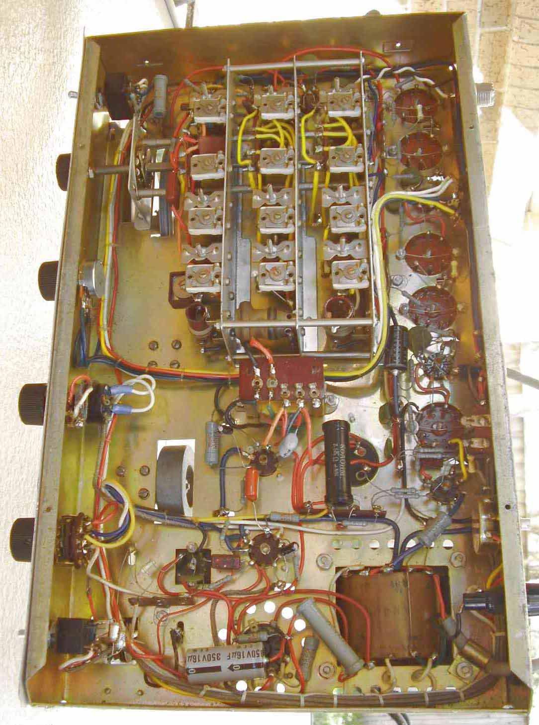
Some variants of the receiver use point-to-point wiring, others -- PCBs. The later has more audio hum due to inferior shielding of PCB tracks compared to screened cables. Some models might have also an 0A2 voltage regulator tube.

Point-to-point wiring.
PCB wiring


Original schematic diagram of HCR-62 --> download here.
There are two unusual things. First, the BFO triode is used as a DC amplifier for S-meter in AM mode. Second, the AM detector diode 6AL5 receives a reduced heater voltage -- 5.1Vac instead of nominal 6.3Vac. Low heater voltage helps reduce hum, but more importantly, it makes the detector more sensitive to small signals. This effect will be described in a separate article on this site.
== MODIFICATIONS ==
Schematic diagram of a modified HCR-62 --> download here.
The following major mods have been done:
1) In the audio amplifier, 6AR5 is replaced by 6AQ5 with higher gain, mild feedback is applied, transformer impedance equalizer circuit R25C5 added, redundant "Send/Receive" switch is now used to turn on high cut-off. It is applied in the form of negative feedback from the plate of V2 to the cathode of V6 via T-bridge C25R42C67. This bridge gives a 4dB rise at 2kHz, then smooth roll-off. Such tone correction cuts off noise, but does not make the sound too mellow or "muffled". Instead it bring up voice and gives sort of retro-gramophone tone to the radio.
2) A decent product detector added for SSB. It is coupled to the capacitive "tap" of the BFO tank. This prevents from the BFO locking on to strong carriers. BFO is overhauled for frequency stability. R45 "Balance" allows to adjust bias on the heptode grid 3 so that direct envelope detection of strong signals (due to anode-bend effect on grid 3) is minimized. C16C56C57 capacitive attenuator reduces the input signal and matches gain of the SSB detector to the AM detector. As a result, overall SSB reception is crystal clear and crispy, as on a real balanced mixer.
3) Transistor voltage regulator is added for frequency stability and better AGC performance. Q1 has an insulated package, and just bolted to the chassis for heat sinking -- very convenient. High voltage Zeners are very noisy, so a compact ceramic capacitor C17 shall be soldered on short legs as close to Zener D1 as practical. D1, C17, R16, R21 shall be kept away from the sensitive input, RF, mixer an IF circuits -- otherwise the radio might pick up the Zener noise due to stray coupling.
4) C18, C69, C70, C71 are added to prevent any possibility of the modulation hum (tuned hum).
5) The most important modification is the addition of the synchronous detector module. It has a proprietary design. It works as a conventional AM detector or as a synchronous detector with automatic unlock-relock function. It generates AGC voltage for the whole receiver, as well as voltage for the S-meter.
Since the IF bandwidth of this receiver is narrow (1.5...2kHz), it is very difficult to receive AM stations in AM mode -- the sound is unpleasantly low, devoid of highs. Synchronous detector is a remedy. By detuning the radio so that only one side band fills the IF bandwidth, yet the carrier is not completely suppressed, synchronous detector gives nice quality with crispy, sometimes even over-accentuated highs. On the shortwave bands the synchronous detector is a treat as well. This familiar nasty distortion caused by carrier selective fading is eliminated.


