Background of audio intermodulation testing
Harmonic distortion factor in audio amplifiers, commonly quoted in audio amplifier datasheets and specifications, is not so critical to the sonic performance as such, since most of the real life signals already contain harmonics. Adding or taking away a fraction of a percent would go unnoticed. The same nonlinearity also produces intermodulation distortion. For example, if two signals at F1 and F2 are applied to a nonlinear amplifier, its output would also contain combination frequencies n*F1+/-m*F2. (Here "n" and "m" are integers, sum thereof is called "order" of intermodulation distortion.) These combination frequencies are absent in the original input material, that is why their appearance at the output, unexpected by human ear, creates sonic impression of "dissonance", "dirty", "foggy", "tiresome" sound, etc. Intermodulation distortion (IMD) is not welcome. IMD factor relates to sound quality more adequately than total harmonic distortion (THD) factor.
A classic two-tone IMD test would require a pair of quality generators, filters and a spectrum analyser which at the same time shall not introduce their own intermodulation. Alternatively, a quality sound card and a special software for digital two-tone generation and spectrum analysis is needed, and who knows how much extra noise and distortion such setup would add due to power supplies, ground loops and interconnecting cables, particularly if the test gear does not have differential inputs and/or galvanic isolation. For the above reasons IMD tests are traditionally considered too complicated and/or prohibitively expensive and are not popular. Thus, simpler and better understood THD tests are more common.
Simple two-tone intermodulation test method
However, IMD test setup can be greatly simplified if a human ear is used as an "instrument". Two tones around 20kHz, differing in frequency by a few hundred Hertz or a kilohertz and of a level corresponding to a typical listening setup are applied to an amplifier under test. Say, for example F1 = 19840Hz and F2 = 20160Hz. Speakers or headphones are connected, as in a normal listening setup, to the amplifier output. A human in a sound-proof room is listening attentively. If the amplifier (to be more correct, the whole audio reproduction chain, including crossovers and speakers) is free from non-linear distortion and intermodulation, the listener will hear nothing -- just silence. Human ear, particularly of a grown-up, usually does not respond to frequencies above 18...19kHz, so the two test tones F1 and F2 will not be heard.
On the other hand, human ear is quite sensitive to 300...2000Hz range and has quite good dynamic range (90dB) comparable to the best spectrum analysers. So, if IMD is present, a soft "whining" noise of difference (beat) frequency F1 - F2 = 320Hz will become audible. Even if some individuums with unique hearing can hear around 20kHz, high frequency tones would feel like some "pressure on the ear", while a low frequency IMD tone can be perceived separately and distinguished. In this example, "whining" is obviously a second order IMD artefact. A fourth order IMD at 640Hz is also can be heard if it is produced by the sound system under test: 2*F1 - 2* F2 = 640Hz. Similarly, even order IMD products can be heard, which are harmonics of the second order IMD artefact.
Thus by the timbre of the "whining" a listener can assess IMD composition. If the 320Hz tone is "clean", "pure" and "mellow", then it probably consists mostly of the second order IMD product, if the tone sounds more "squeaky", "harsh", "screaming", etc., it indicates presence of higher order products. This way not only can a human ear estimate the amount of IMD, but also roughly assess its spectral composition -- without any sophisticated and expensive spectrum analysers! One of the advantages of the described audible IMD testing is that test is relevant to a real sound system setup and actual typical listening environment -- actual amplifier, actual speakers with given sensitivity, real room size, comfortable listening level. On the contrary, an artificial laboratory test is usually performed into a dummy load, at some arbitrarily set signal level (usually close to maximum rated power) and may not be relevant to the actual mode of a particular amplifier usage.
Notes:
a) Such test with two close frequencies can not measure third (and other odd) order IMD products. For example, third order IMD products would be sitting at 19520Hz and 20480Hz and would not be audible.
b) Such test is more suited for single-ended class A valve amplifiers which tend to generate even order harmonic distortion and IMD, as opposed to push-pull and solid-state amplifiers which predominantly produce odd order IMD products. However, as will be discussed below, this test is useful for push-pull amplifiers too.
c) Such test is more suited for tube amplifiers which typically have mild and almost uniform negative feedback loop gain over the audio range. Therefore IMD factor is more or less constant over the audio range. In the transistorised amplifiers feedback loop gain is quite high at low frequencies, so the relatively low 320Hz beat IMD tone would be greatly suppressed by the feedback (unless the distortion takes place right in the first differential gain stage or the front end operation amplifier). In "real life" situations, where F1 - F2 are higher, IMD artefacts can be larger. Thus, for a transistor amplifier, this test usually gives overly "optimistic" result.
Intermodulation test signal generator
In principal, it is not difficult to generate two frequencies about 20kHz differing by 300...400Hz or so, but it would be a bit complicated: a crystal oscillator, frequency dividers, filters to obtain sine waves from square wave signals, or perhaps even a microcontroller to program a DDS synthesiser.
There exists a simpler way -- balance-modulate a 20kHz carrier by a low frequency signal. A block diagram of such IMD test generator is shown in Fig. 1.
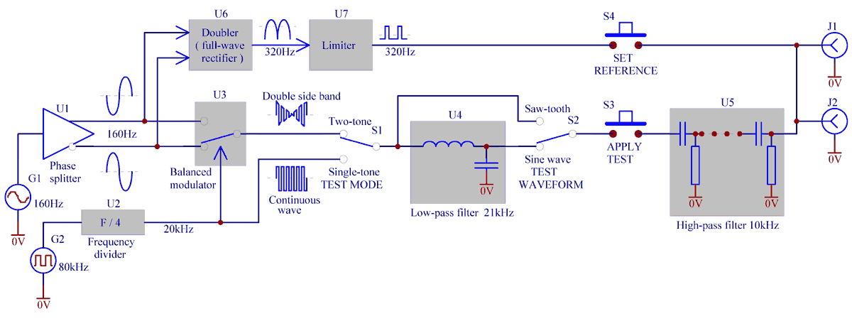
Fig. 1. Block diagram of a two tone IMD test generator.
A simple RC oscillator G2, divided by U2 to get 50% duty cycle, produces a square wave "carrier" of about 20kHz. A CMOS switch U3, performs a role of a balanced modulator, where the carrier gets modulated by a 160Hz sine wave. This modulating 160Hz signal, in turn, is created by a Wien bridge bases oscillator G1 and a phase splitter U1. A double side band (DSB) signal appears at the U3 output (Fig. 2). Since one side band is 160Hz below the carrier, and the other side band is 160Hz above the carrier, and the carrier is suppressed, then the frequency difference between the sidebands is 320Hz -- double modulation frequency. This is a two-tone IMD test signal.
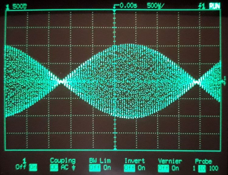
Fig. 2. A 20kHz carrier, balance modulated by a 160Hz sine wave (double side band).
While pressing a momentary switch (pushbutton) S3 "APPLY TEST", the test signal is being fed to the output connectors J1 and J2 and from there -- to the amplifier under test. A sixth order passive high-pass filter U5 is intended to virtually eliminate all low frequency possible spurious components from the test signal. Those may be created by a modulation frequency residue (and its harmonics), nonlinear distortion products of the operation amplifiers and even nonlinearity of the capacitors and the inductor. Only high frequency DSB test signal is allowed to pass tho an amplifier under test. Naturally the "carrier" is square wave, but due to high frequencies accentuation in the high-pass filter U5, the test signal (carrier) would assume the following saw-tooth (Fig. 3) waveform.
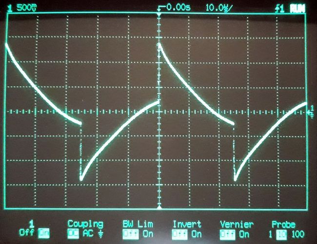
Fig. 3. Test signal (carrier) waveform in "Saw-tooth" mode.
Though useful in certain cases (which will be explained below), such test signal is not conventional for the realm of audio, where sine waves dominate.
So, by means of switch S2 "TEST WAVEFORM" a low-pass filter U4 can be cut into the signal chain to make the test signal carrier more "conventional" -- almost like a sine wave (Fig. 4). Minor distortions would not affect IMD test results.
Fig. 4. Test signal waveform (carrier) in "Sine wave" mode.
Note that it is also possible, by means of switch S1 ("TWO-TONE / SINGLE TONE") to apply an unmodulated carrier (either sine wave (Fig. 4 or saw-tooth (Fig.3), depending on S2 position) to the amplifier under test. It may be useful for some amplifier tests, other than IMD. This mode will be discussed below.
The test generator also includes a "reference" signal path, which consists of a modulation frequency doubler U6, a limiter U7 to produce a rectangular 320Hz signal of about 30% duty cycle, and a pushbutton S4 "SET REFERENCE" to pass this reference signal to the amplifier under test. Purpose of the reference signal is to set a comfortable listening volume, so that a subsequent IMD test signal is applied with about the same r.m.s. level. The test generator is so designed that it produces equal output of about 400mVrms in any mode for any test waveform.
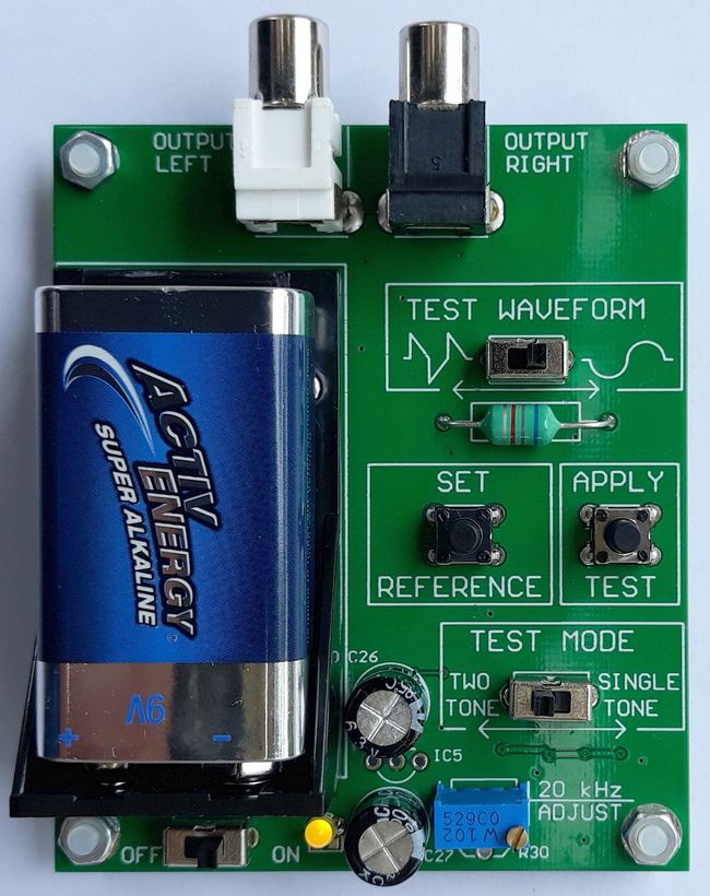
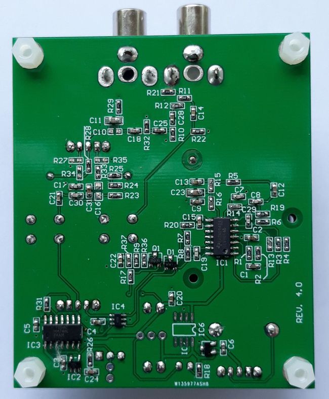
The described above test generator is constructed on a simple PCB 68mm x 80mm (Fig. 4, Fig. 5) and utilises common genetic components. It is battery powered which minimising the risk of picking up hum and noise from ground loops.
Fig. 4. Top view of the IMD test generator module PCB. A LED indicates power on.
Fig. 5. Bottom view of the IMD test generator module PCB.
Intermodulation Distortion test procedure
The following test procedure will explain capability of this simple instrument better.
1. The IMD tester produces about 400mVrms of audio, so is to be connected to AUX or TAPE input of an amplifier under test, or to the preamplifier input, if it is always used together with the amplifier. Both output RCA connectors of the tester are paralleled, so both channels of a stereo system can be tested simultaneously. It is recommended however, to minimise ground loops and avoid hum, to run a single well shielded cable, e.g. 75 Ohm coaxial cable and split the signal physically closer to the amplifier. Usual speakers can be used in the test. Listening room should be noise proof as much as practical. A listener should take his/her usual position in the listening room. In short, test setup and environment should resemble normal listening arrangement.
2. Set VOLUME of the amplifier under test to minimum, tone controls to FLAT (or bypass), if possible, disable LOUDNESS. Power the tester ON (LED will illuminate), press SET REFERENCE button and gradually increase VOLUME on the amplifier. You will hear 320Hz tone, rich with harmonics, which imitates (or emulates) sound of an audio programme. Keep increasing VOLUME on the amplifier until the sound reaches loud but not overly loud uncomfortable level -- the level at which you would normally listen to your system or slightly louder than normally, to test the "worst case". Release the SET REFERENCE button and give your ears some time to "relax" and re-adapt to the quiet ambience.
3. Set TEST MODE to TWO-TONE, WAVEFORM to "sine wave" and press APPLY TEST button. At this moment the two-tone signal with the same level (about 400mVrms) will be applied to the amplifier (and the whole sound system, of course). Ideally, if your sound system is perfectly linear, you should hear nothing (apart from soft clicks when pressing the button) -- just silence. If you hear a whining tone at 320Hz -- you have intermodulation problem somewhere in the signal chain, not necessarily in the amplifier alone. You will actually hear how loud the IMD is. If it is barely perceptible, or ideally not discernible at all, consider your amplifier and sound system has "passed" and can be considered an "ideal" "reference" amplifier, not likely to add sonic coloration -- at that given signal level typical for your listening preferences. Note: Do not hold APPLY TEST button continuously for longer than a few seconds, as tweeter voice coils may overheat.
4. You may repeat the above test (step 3) with WAVEFORM switch now in "saw-tooth" position. The "pointy" test signal now is rich with harmonics around 60kHz, 100kHz, etc. If your amplifier is well designed, it will internally naturally smooth the sawtooth, and this test will be no different to step 3. However, in a badly designed amplifier with excessive bandwidth this spiky waveform would "provoke" slew rate limiting, diagonal clipping, etc., which will give rise to higher distortion, and the 320Hz whining tone will be heard louder. Similarly, if a tube amplifier with improperly designed feedback is marginally stable, such saw tooth stimulus would provoke excessive ringing with consequential clipping which would also lead to larger and louder IMD artefacts. Thus, this simple test can indirectly assess quality of your amplifier design.
5. If you definitely can hear the IMD whining, and it bothers you, do not haste to blame the amplifier. IMD might be caused not only by the amplifier, but by other factors, such as electromechanical nonlinearity of the speaker drivers, crossover circuits with their ferromagnetic inductors, unstable unreliable oxidated switches and relay contacts, loose connectors and terminals, dirty volume control and tone control potentiometer wipers -- generally by any bad or unstable contacts in the signal path. Contamination of the contact surfaces by chemically dissimilar substances might make them work as diodes (like crystal detectors) and rectify the test signal envelope, thus creating IMD. Therefore, while keeping APPLY TEST button pressed, try to gently tweak source selector switches of the amplifier under test, speaker selector buttons, MUTE, LOUDNESS buttons, controls, RCA connectors, tighten speaker terminals, even tap speaker protection relay if accessible. Pay attention to possible intermittent bursts of IMD "whining". Note again, that APPLY TEST button should not be held continuously for long periods of time.
To exclude the speakers as the source of IMD, try to locate from where the sound is coming. If it seems like coming from the woofer or midrange drivers, then most likely IMD is created in the amplifier, less likely in the crossover circuit. If the sound seems to emanate from the tweeters, then the tweeters are creating IMD. The only remedy is to change the speakers or temporarily disconnect them to prove the theory.
Unfortunately it is practically impossible to separate crossover filters distortion from the amplifier distortion. Fortunately, crossover circuitry is unlikely to create second order IMD. It is more likely to produce third order distortion, as nonlinearity of ferromagnetic cores of the inductors or non-polarised electrolytic capacitors is "symmetrical", and this test is not sensitive to third order IMD. There is only one reliable way to eliminate crossover filter distortion -- use quality components. Refurbish your crossovers with quality metal film polypropylene capacitors, air-core inductors (though they are larger and heavier), stable overrated resistors (if any) with low temperature coefficient, ensure reliable contacts -- soldered or tightly fit screw or spade terminals.
Some fancy speakers might have such frills as LED level indicators or even needle VU panel meters. Such meters are driven directly by the speaker voltage through diode rectifiers. Needless to say, a diode rectifier makes speaker impedance non-linear. If an amplifier has low output impedance, as common in transistor amplifiers, this minor speaker impedance nonlinearity would not have any effect. However, for valve amplifiers, which have relatively high output impedance, a level indicator diode detector might create noticeable IMD. For that reason it is highly recommended to disconnect all speaker level indication circuitry if present, particularly if your sound system is based on a valve power amplifier.
6. To estimate how low the output impedance of your amplifier is, you can put the amplifier to a harsher IMD test. Rerun step 3 of the test, but deliberately make the load substantially nonlinear. To do that, connect a 4.7...8.2 Ohm resistor in series with a 3A Schottky (e.g. 1N5822) or ultrafast diode (not 1N4007 or 1N5407!) in parallel to the speaker directly at the amplifier speaker terminals. An amplifier with low output impedance and strong feedback will still be able to maintain linearity, and 320Hz IMD whining will not be heard. A "feeble" amplifier with weak feedback would whine loudly, as due to the non-linear load, positive and negative excursions of the output voltage will become unequal. This test can help assess output impedance and feedback strength, but is quite irrelevant to sonic quality of an amplifier, as in real life no one would deliberately add nonlinear loading to the speakers. As mentioned earlier, passive VU metering should be removed from the speakers.
7. If your amplification chain under test includes a preamplifier, it is recommended to try to remove or bypass it and redo the tests. In many cases, a preamplifier creates more IMD than the final power amplifier itself. It particularly applies to those simple tube "preamps" which boast to give a "unique tube flavour" to the sound. Such preamps comprise a single tube stage and definitely produce significant amounts of second order IMD.
8. The IMD tester described in this article can also be handy to balance push-pull power stages of valve amplifiers. Usually balancing is done by matching the tubes and/or adjusting grid negative bias to obtain equal quiescent current. With this tester the process is much easier. Run IMD test as per step 5 and adjust the bias to minimise the IMD whining. This point will correspond to the most symmetrical transfer function (second order distortion is cancelled), in other words to the best balance.
9. A few comments on the single-tone (continuous wave) test.
Firstly, it can test speaker drivers for susceptibility to parasitic parametric subharmonic oscillation. To understand what this phenomenon is, imagine a vibrating surface, for example, a facing up cone of a large speaker, buzzing at say 50Hz, with a light-weight object as a pea or ping-pong ball placed on its cone. Will this lightweight object vibrate with the cone? No. The cone might well be pushing the pea upward, but gravity may not be sufficient for the pea to follow the cone movement downwards. On the downward movement the pea will lose contact with the vibrating cone. Will the pea hover just touching upper "envelope" of the cone vibration? Neither. The pea or ping-pong ball is kicked up fast but free-falls down slower. As a result, it would quite erratically roll and bounce on the vibrating cone. In other words, frequency of the pea bounce becomes much lower and somewhat random, compared to the cone vibration frequency. Such behaviour is due to extremely non-linear coupling between the cone and the ball -- tight connection on the way up, no connection on the way down. Similarly, if a tweeter driver dome has loose, non-uniform and mechanically non-linear coupling to its voice coil, the tweeter might, when excited by 20kHz, start producing some sub-harmonic or erratic "screeching" noise at lower frequencies (2...10kHz), which become audible, but unmistakably different from a 320Hz IMD whine. So, such single tone test can verify quality of the tweeters (or dual-cone full range speakers).
If you have an amplifier of an unknown origin, particularly if it suspiciously small, lightweight and yet surprisingly powerful, if it is "hybrid", if it is purchased online, there is a chance that this amp is class D (switching), possibly with a tube in front for the "valve" sound. Needless to say, class D amps are no-no for the audiophiles. To check, without opening the amplifier and inspecting its PCB, apply a single-tone test with saw-tooth test waveform. If your amplifier is switching, then most likely harmonics of the test signal will start producing beats (aliasing) with the class D amplifier switching, resulting in some audible noise.
Secondly, similarly to step 5, this test can help reveal unstable and "dirty" electrical contacts in the signal path. If you hear soft rustling or crackling sound while you hold APPLY TEST button and gently jiggle amplifier controls and connection cables, the you have bad contacts issue.
Thirdly, this continuous wave (single tone) test can identify power supply ripple rejection problem in your amplifier. If it is the case, then while pressing APPLY TEST button, you will hear a soft 100Hz (or 120Hz for the countries with 60Hz mains) hum. What happens is -- during the test, the amplifier draws higher supply current, voltage ripple on the supply rails increases, and if supply voltage filtering is inadequate and/or power supply rejection ratio is poor, this supply ripple will induce hum in the signal path. This test works for class AB valve or transistor push-pull amplifiers, and obviously will not work for a single-ended class A with constant supply current.
Finally, this test may be a "survival" test for some vintage transistor amplifiers, particularly if it is run with a saw-tooth test waveform. Old push-pull transistor amplifiers use "slow" power transistors which are not able to cut-off quickly on this high slew rate test signal. Thus, a destructive shoot-through current may develop in the power stage, particularly in case of vulnerable Germanium transistors prone to thermal runaway). Usually just before breakdown and destruction a "scary" rumbling hum is heard followed by a "pop". Be careful with this test though, as a dying amplifier may take out the speakers by passing supply voltage onto them through the blown output transistors.
Summary of the benefits of the simple IMD test generator
- Inexpensive, simple, convenient;
- Does not require sophisticated expensive test equipment;
- Does not require engineering skills to operate test equipment;
- Does not to interpret and make sense of the formal results;
- No risk of introducing noise and hum, as it is battery powered;
- Tests the whole signal chain of a sound system, not solely an amplifier;
- Able to identify and gives clues to the causes of subtle problems;
- Allows to assess quality of an amplifier design (by applying the "provocative" saw-tooth test waveform);
- Testing is run in real time, "live", able to capture elusive intermittent issues, e.g. bad contacts while jiggling controls;
- Testing is performed under typical listening conditions -- actual speakers, real cables, realistic signal level, therefore it is relevant;
- Subjective -- you can actually hear the amount of IMD your system generates, and can judge for yourself if it is worrying or negligible;
- Useful for other experiments (e.g., vintage amp survival test, balancing push-pull amps, identifying class D amps).
Conclusion
This IMD test generator, though simple, is extremely versatile and useful.
If you have several amplifiers at your disposal, you can test them in real listening conditions. You might find that a $100 amplifier is no better than a $10,000 one. This tester is an eye-opener.
You might be able to do some research to establish a general relationship between IMD volume (loudness) and the sonic perception. You might find that those "perfect" amps with no audible IMD whining in reality sound too "sterile" and lifeless, while the amps in which the IMD tone is audible, but soft, sound the best. You might be able to find the maximum acceptable level of audible IMD, beyond which sound indeed becomes distorted, rough, "dirty".
If you are purchasing an amplifier with a demonstration then it is handy to carry such a generator in your pocket and give this amplifier a "test drive" before purchasing. You and the vendor might be surprised/amazed/pleased/disappointed with the results, and such a test can save money, time, and trouble.
The tester is good for picking subtle intermittent problems in the signal chain, like for example, broken strands in the speaker wires. (In this case, a single tone test would cause soft crackling when bending the cable.)
You may even use this tester to exterminate poorly designed weaklings -- apply single tone saw-tooth test and crank volume and tone controls to maximum. Do not even connect a load. If an amplifier blows up after a few seconds of this torture (a transistor one -- because of shoot-through currents caused by slow-recovery transistors, or a tube one -- due to tubes arcing and transformer insulation breaking down) -- then the amp rightfully deserves a rubbish dump.
For questions and to purchase a doubler/modulator module for such project feel free to use the contact page of this website.


