Basic primitive tube pentode amplifier
Some claim that a tube amplifier without negative feedback delivers the best sound. It might be true for a well designed triode or ultralinear amplifier, but not for a classic (in fact, primitive and boring) pentode / beam tetrode one as shown in Fig. 1.
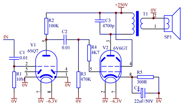
Fig. 1. Basic amplifier with no feedback
An amplifier similar to that one can be found in majority of inexpensive radios -- from mid 30's to early 60's. Its performance is very poor by todays standards. High inductive output impedance provides no damping for the speaker, hum is not suppressed, bandwidth is narrow, frequency response is not flat, etc. The biggest problem is caused by an undersized (saving every cent) output transformer with insufficient magnetizing inductance (as low as 5H) and large leakage inductance (up to 300...500mH). As a result, such amplifier efficiently reproduces from 150Hz to 7kHz. At low frequencies (50...100Hz), distortion reaches 25...35%. It is not surprising: the output tube V2 works into low and reactive load and easily generates 10...15% of plate current distortion. The transformer, due to its low inductance, suppresses the fundamental, but passes the harmonics, plus adds its own caused by magnetic non-linearity. Thus the circuit turns into a harmonics generator rather than amplifier.
Introduction of a simple resistive negative feedback (Fig. 2) does improve sound quality, but only at low listening levels.
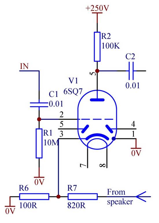
Fig. 2. Resistive negative feedback
Resistive negative feedback lowers output impedance and attempts to broaden the bandwidth. For example, a typical 10dB feedback would stretch frequency response from 150Hz...7kHz to approximately 50Hz...20kHz -- beyond what the transformer can naturally reproduce. As a result, the amplifier struggles to reproduce low and high frequencies by driving/pushing the output tube hard. Overloading and clipping occurs, which sounds even worse than without feedback. In a sense, this phenomenon proves the point that negative feedback sounds worse than no feedback at all.
Frequency dependent negative feedback
A solution to the problem is making negative feedback frequency dependent so that its characteristics matches natural capabilities of the output transformer (and a speaker). In Fig. 3, by way of C5, negative feedback is designed to roll off the gain from 150Hz down. The amplifier no longer struggles to amplify frequencies it is not capable of doing well. Overdriving and overloading by low frequencies is reduced -- sound becomes much better.
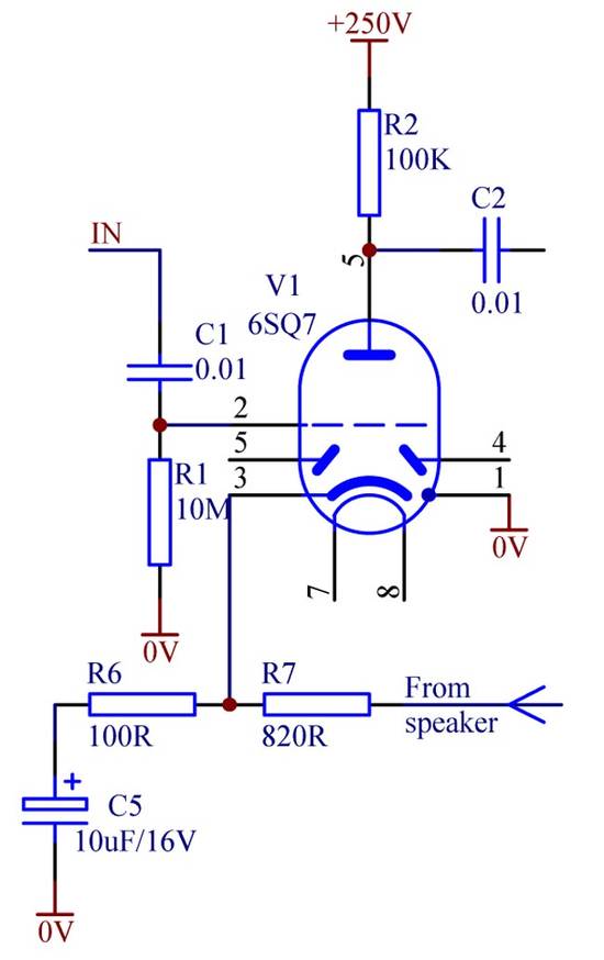
Fig. 3. First order low frequency roll-off negative feedback
To deepen feedback even steeper at low frequencies, a second order shaping circuit can be used (Fig. 4).
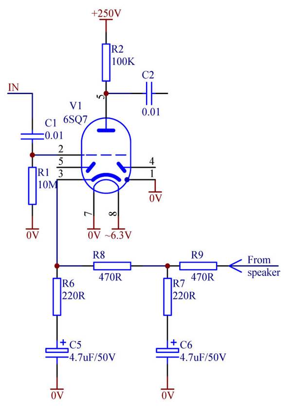
Fig. 4. Second order low frequency roll-off negative feedback
Here two RC circuits are cascaded, creating together a 12dB/decade steep roll-off below 150Hz. At 50Hz the feedback reaches its full depth -- 100%. Sound becomes dry, but exceptionally crisp and transparent. The deep possible feedback down to 50Hz gives an additional benefit. In some radios the output transformer is located physically too close to the mains power transformer and picks up stray magnetic field of the later. It causes some hum, and the only way to reduce it (apart from relocating the transformer) -- is to provide maximum amount of feedback at hum frequency.
Two stages of RC circuits (R9C6 and R8C5) provide significant phase lag, which is good to compensate for phase advance created by the transformer, decoupling circuit R3C2 and self-biasing circuit R5C4. Do not select excessively large cathode capacitor C4. The best is to have R5C4 time constant of the same order as R9C6, so that its phase advance is hidden by the phase lag of the feedback circuitry. C2R3 should be set to just under 50Hz. It is better to select it empirically to avoid infra-low frequency peaking.
High frequency smart feedback
In a similar fashion, it would be reasonable to restrict high frequency range of the amplifier by deepening negative feedback above he natural capability of the output transformer. A problem here is that, if the feedback is taken from the speaker, the amplifier will most likely become unstable when the feedback reaches 100%. There are too many poles caused by the following: (a) winding capacitance of the output transformer, (b) leakage inductance of the transformer, (c) stray capacitive loading of V1 plate / V2 grid. However, a solution exists -- to remove the troublesome output transformer from the feedback loop (Fig. 5).
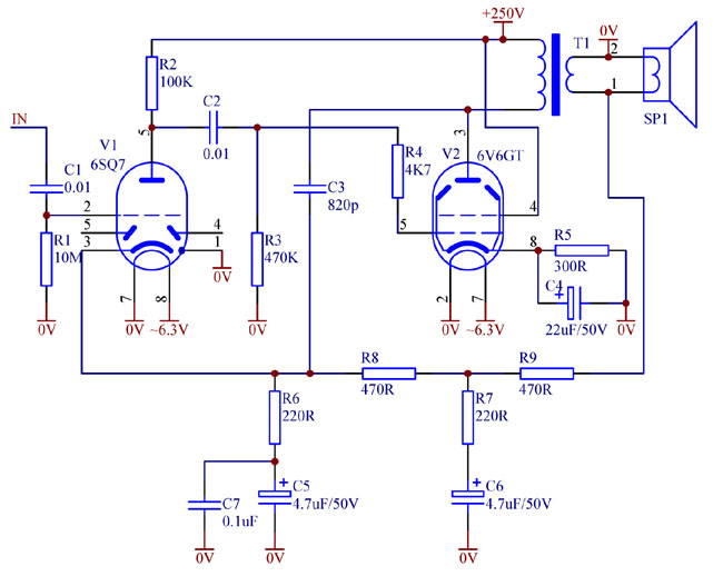
Fig. 5. High frequency smart negative feedback bypassing the output transformer
By selecting C3 it is possible to set the high end of the bandwidth to match the intrinsic performance of the transformer. For an amplifier used in an AM radio, it is usually around 7kHz, which will reduce undesirable whistles from the adjacent stations and also suppress 455kHz residue coming from the AM detector. C3 should be rated at 630V minimum, better 1...2kV, NPO/COG or mica dielectric is preferred. For stable and controlled performance at high frequencies, it is recommended to shunt C5 with a ceramic capacitor. It is also possible to make C5 and C6 of multilayer ceramic capacitors with X7R or X5R dielectric rated at 25V. C3 value is to be selected to achieve desirable roll-off frequency. However, it is better to assess "natural" frequency range of the stage. Feed a signal from a low impedance audio oscillator directly to the grid of V2 and observe response on the plate (or speaker). Usually it will peak at 7...12kHz due to the winding leakage inductance and distributed capacitance. Note the resonance frequency. It is the "natural" limit (capability) of the transformer. It is recommended (by adjusting C3) to set the high roll-off of the feedback at this frequency or lower, but not higher.
Instead of having a smooth 6dB/octave, one might introduce a T-bridge, creating some quasi-resonant peaking at the top end with a steep roll-off beyond (Fig. 6). Peaking usually sounds better, particularly if the bandwidth of the amplifier (and a radio receiver) is too narrow.
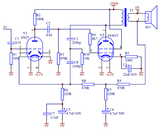
Fig. 6. Second order T-bridge based high frequency negative feedback
Selecting C3, C8 and R10 (with C3 and C8 about the same order of magnitude), one can control the cut-off frequency and the amount of quasi-resonant peaking. These components can be made switchable for different listening conditions. Alternatively R10 can be a made a variable resistor performing sort of tone control, similar to what described here.
Hopefully the smart feedback tips in this article can help transform your old simple tube radio in something more listenable. Note that introducing feedback requires lifting cathode of duo-diode-triode valve V1 off the ground. It will become impractical to use the diodes of V1 in AM/AGC detector(s). Therefore it is recommended to use Schottky diodes 1N5711 instead (do not forget to realign the IF transformer). Most likely, sensitivity of the detector will improve (as explained here).
