Audio amplifiers in low cost radios quite often were very simple, basic and primitive. An example of a generalised circuit of such an amplifier is shown below in Fig. 1.
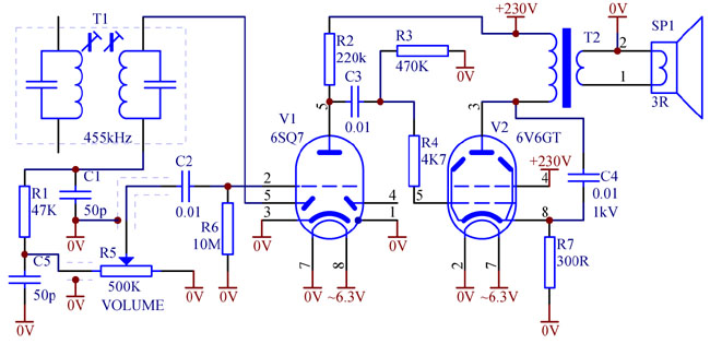
Fig. 1. Basic audio amplifier circuit without feedback
There is nothing at all spectacular about this circuit, apart perhaps C4 connected not across the output transformer, but to the cathode of V2. Purpose of this capacitor is to cancel inductive component of the plate load at high frequencies. The inductive component is caused by the speaker inductance and leakage inductance of the transformer. In this circuit, current through C4 is not returned to ground, but "recycled" back to the cathode, boosting gain at high frequencies. Thus this arrangement works as a smart tone control, boosting highs by about 3dB and making the sound a little better.
Other than that, overall performance is poor. With no negative feedback, the amplifier has large output impedance, does not damp the speaker which results in a boomy sound. Harmonic distortion easily raises with raising volume. Hum is not suppressed. It is independent of volume control position and may become quite annoying at low listening levels. While restoring such a radio, it is possible to reduce hum by increasing capacitors in the supply filters, to some extent, to avoid excessive stress to a rectifier tube.
The nastiest form of hum is the hum caused by stray magnetic coupling between the audio output and the mains power transformers. Nothing apart from relocating of the transformer(s), can be done to get rid of it.
Therefore it has been tempting to control volume not by merely attenuating input signal, but by changing feedback. One way of doing it is to connect the "cold" end of the volume control potentiometer to the output, not to ground, as shown in Fig. 2.
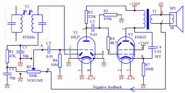
Fig. 2. Simple variable negative feedback volume control. This solution is impractical.
This solution is shown to illustrate the idea, but it is impractical for the following reasons.
Firstly, open loop gain G from point "A" to point "B" is about 15...25 depending on the tubes used. Therefore with volume control R5 set to maximum, input impedance of the amplifier will become R5/(G+1), that is about 25KOhm. Such low impedance will prevent the amplitude detector from working properly. It will significantly shunt the IF transformer, distorting passband selectivity curve and reducing IF gain of the radio. Detector distortion will increase as well. It is common knowledge that maximum modulation which a diode detector can handle without distortion equals a ratio of AC load to DC load of the detector. In this circuit, AC load is about R5/(G+1) and DC load is R5+R1. Thus, in this example, with the volume control set to maximum, the detector will handle only up to 13% of amplitude modulation. Clipping will occur at higher modulation levels.
Secondly, this amplifier is prone to instability. At zero or low volume setting, the amplifier runs with almost 100% negative feedback and with a rather high loop gain of 24...28dB. At low frequencies there are three phase advancing differentiating elements: C2R6, C3R3 and the transformer. Unless utmost care is taken to make only one of them dominant, the amplifier is likely to oscillate ("motorboat"). At high frequencies, phase lag is created by C4, leakage inductance of the transformer, inter-electrode capacitances of V1 and V2, and on top of that, by portion of R5 together with input capacitance of V1, magnified by its Miller effect. Again the circuit is likely to become unstable somewhere at middle volume setting.
This principle of variable feedback volume control was actually implemented in some radios, like Calstan, but the loop gain was reduced, as shown in Fig. 3.

Fig. 3. Variable negative feedback volume control practical circuit.
Here the loop gain from "A" to "B" is reduced to about 6dB. In this case it is not difficult to achieve stability. AC load impedance reflected to the AM detector in this case reduces only by half at maximum volume position, and the detector can handle up to 50% AM, which is not ideal, but acceptable in low cost radios. As any trade-off, this circuit offers only a modest benefit: hum and distortion get reduced only by 6dB, and speaker resonance is damped only by 50%.
Is it possible to get full advantage of the variable feedback volume control and somehow avoid low input impedance and stability problems? The answer is "Yes".
An original solution is presented in Fig. 4.

Fig. 4. Dual-gang composite variable negative feedback volume control.
Here a dual-gang volume control potentiometer is used. R5A attenuates input signal, while R5B controls feedback (loop gain). Obviously at zero volume setting input resistance equals to the value of R5A (1MOhm in this example). Feedback loop gain is maximum (about 25dB) as points "B" and "C" are connected together.
At full volume input resistance is also 1MOhm since point "B" gets grounded.
Somewhere at medium volume input resistance somewhat drops, but to an acceptable value of 400...600KOhm. Exact minimum input resistance value depends on the curve of the potentiometers used, as well as on the size of an optional resistor R8. The lower R8, the "faster" volume raises with the shaft turning, and the higher the minimum input impedance becomes.
At low to medium volume, which is common when listening to a kitchen radio, the amplifier operates with high loop gain of around 20dB. Special measures are taken to ensure stability.
Firstly, the grid leak bias forming circuit R6C2 is connected in series with the grid. Such arrangement helps eliminate a low frequency null -- at infra-low frequencies V1 grid is DC coupled, so to say. The remaining two nulls (C3R3 and the transformer) can not cause instability. They can cause some very low frequency peaking though. If this happens to be the case, then it is recommended to increase C3, making the transformer a dominant null.
Secondly, to maintain stability at high frequencies, a pole at input of V1, caused by its Miller-enhanced input capacitance must be compensated. First of all, capacitance to ground shall be kept to minimum. For that reason the screen of the signal cable running from R5 to the tube is not connected to ground, but to the output. Low speaker impedance virtually grounds it, so it continues to play its direct noise shielding role. At the same time, a small capacitance of this cable (3...10pF) is used as a phase advancing element in the loop, which cancels out Miller effect related phase lag. It is similar to a common practice of placing a small capacitor across a feedback resistor in audio amplifiers. The piece of the cable shall not be too long though (usually 50...100mm) to avoid high frequency roll-off. Needless to say, the shield shall be isolated from the chassis, rewiring might be needed, as in some old radios the screened cables do not have outer sheath. The remaining poles -- interstage, C4 and transformer leakage -- are easy to control, one of them (C4) usually becoming a dominant. If C4 does not want to become a dominant pole, then another dominant pole can be created, for example by connecting a couple of hundred picofarad from V1 plate to ground or a few picofarads between plates of V1 and V2 -- like in an operation amplifier. Leakage inductance pole is not a great worry in a radio, because the speaker has an inductive component virtually cancelling out that pole.
Thus, the above "tricks", particularly a piece of the screened cable help maintain stability of the amplifier with deep negative feedback.
Deep negative feedback (around 20dB) at low and medium listening levels ensures very low distortion (under 0.5%), low output impedance for excellent speaker damping and tight crispy sound and impressive hum suppression. The radio becomes a pleasure to listen, like Hi-Fi.
Obviously implementation of such modification requires a dual-gang potentiometer. Those are quite common nowadays, but not doubled up with ON/OF switch. So if in the radio you are restoring the volume control is not doubled up with the switch, this modification is highly recommended to improve performance of your radio.
The mod is also recommended in the audio stages of vintage communication receivers, mainly to reduce annoying and tiring hum when using headphones.
Of course the principle of variable feedback volume control in general can be applied to any Hi-Fi valve amplifier, but one must be careful, because it might be difficult to ensure unconditional stability over the whole range of volume control and with any speaker or when running into a capacitive load. Even capacitors shunting self-bias resistors might add to problems, as each of them contributes to phase advance at low frequencies. To widen audio bandwidth in a Hi-Fi amplifier, volume control potentiometer value should be reduced to 50...250KOhm.