T-bridge tone control
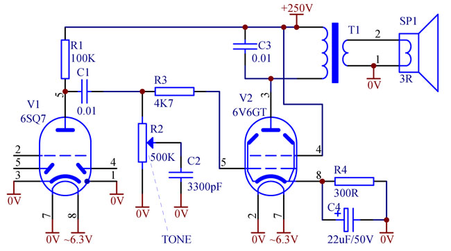
Some vintage valve radios use crude and primitive tone control, as shown in Fig. 1.

Fig. 1. Basic tone control circuit
It is intended to cut high frequency whistles often heard on short waves due to interference from adjacent stations. With the tone control R2 fully engaged, capacitor C2 together with plate resistance of the first stage valve V1 forms a low pass filter with about 1kHz corner frequency.
Partial engagement of R2 does not vary the corner frequency, but only changes the attenuation of all the frequencies from 1kHz up. Thus, if a listener needs only to cut the most high pitched interference, the whole range from 1kHz up will be muffled. This makes the sound low, booming, unpleasant and even less readable than with full bandwidth.
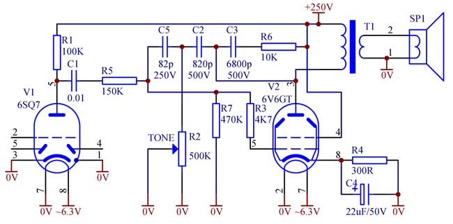
It would be better if the tone control changes the corner frequency, rather than attenuation of the whole range. Such a solution is possible and it is illustrated by Fig. 2. Tone control elements are connected into the local feedback loop around the output tube V2.

Fig. 2. Feedback tone control with T-bridge
When R2 is set to maximum, it has almost no effect, and capacitors C2 and C5 (in series) get connected virtually between plate and grid of the output tube. Their capacitance, magnified by Miller effect of the tube V2, together with R5 creates a pole, cutting frequencies above 500...1000Hz. This is the position of maximum highs cut.
When R2 is set to zero, C5 mildly loads the grid of V2, creating a pole at about 10kHz. This is the position for wide frequency range.
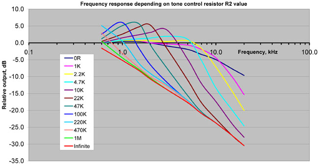
In the intermediate position of R2, time constant R2C2 determines the corner frequency when the feedback kicks in. There are two cascaded phase advancing differentiating circuits in the loop: C2R2 and C5R5. It means that at certain frequencies phase shift in the feedback loop can exceed 90 degrees and the feedback can become somewhat positive rather than negative. Thus some resonance-like signal boost takes place before cut-off. Plot Fig. 3 shows frequency response of this amplifier at different positions of R2.

Fig. 3. Frequency response at different positions of the tone control
As mentioned above, at zero setting the frequency curve exhibits mild sloping toward the high end. At 1...2KOhm the response is getting flatter and developing a distinctive cut-off corner. From 5KOhm on some peaking is developing, while the corner cut-off getting more pronounced and moving to lower frequencies. Peaking reaches +6...7dB. The curves show distinct separation between pass band and stop band.
Peaking feature of such tone control circuit creates several benefits.
Firstly, accentuating frequencies just below cut-off helps keeping a balance of low and high frequencies. It makes the tone more "balanced", less muffled and speech more readable.
Secondly, even if there is no interference to suppress, this tone control can somewhat broaden frequency range of a radio if the peak created by the tone control is set to compensate for the IF bandwidth related roll-off. In other words, this tone control changes coloration of sound rather than simply muffling it.
Thirdly, limiting audio bandwidth actually improves sound quality under carrier fading conditions -- harsh distortion caused by phase reversals gets less noticeable.
Practical design considerations
1. Though R5 slightly reduces the overall gain of the amplifier, its purpose is to increase output impedance of the first stage and make it less dependent on the plate resistance of a particular tube V1.
2. Damping circuit R6C3 is recommended as opposed to a simple capacitor. This circuit damps the resonant effects related to the output transformer leakage inductance and speaker inductance. As has been mentioned above, peaking results from above 90 degrees phase advance in the loop. Leakage inductive component in the plate load of V2 would add more phase advance at high frequencies, which might result in the excessive peaking. Too much peaking might produce undesirable "ringing" in the audio tone. Generally, the larger the R6, the more peaking will result.
3. It is recommended to use tone control resistor R2 with "A" curve (same as commonly used for volume control) to achieve smooth sound coloration control in the high range, at low values of R2.
4. Capacitors C1, C2, C3, C5 shall be adequately voltage rated.
5. Value of C2 is not critical -- can be from 470pF to 2200pF. Family of tone control curves (Fig. 3) will look similar with any value of C2, but the higher the value, but the corresponding values of R2 are inversely proportional to C2. With a larger C2 peaking becomes somewhat more prominent.
When repairing or restoring vintage radios, it is recommended to replace crude tone control (Fig. 1) by the T-bridge feedback option (Fig.2). It will improve sound quality.
It is also possible to use the same T-bridge tone control concept to a general negative feedback loop, for example, from the plate of V2 to the cathode of V1. In this case C2 and in particular C5 will be larger, R2 -- smaller, R5 -- not needed. Such circuit is usually not practical though, as V1 cathode is typically grounded and not available for the feedback application.
