Introduction
Restoring and collecting old tube AM radios may be an interesting and rewarding hobby, but the problem is -- AM broadcasting is gradually being phased out, both on the medium waves and on the short wave bands. While AM broadcasting may be still available in the large cities, it is not so in the remote rural areas. Besides, audio quality of AM is not so good by the modern standards. So, unfortunately, vintage valve radios, from being useful devices, are becoming more and more just "dust collecting" items.
The situation is even more drastic in Australia, where FM broadcasting practically began as late as 1975, when the tubes have been already squeezed out by the transistors, so Australian FM tube radios simply do not exist.
On the other hand, FM broadcasting is not going to disappear soon, as it is still popular and provides high quality audio.
In this situation it would be reasonable to somehow try to add FM reception to AM vintage valve radios, making them listenable and not compromising their authentic looks.
Integrated FM tuners
Fortunately, technological advances in the electronics allowed to greatly simplify FM tuner design. Nowdays, many single-chip solutions are available. Older integrated circuits, like TDA7000, were tuned by conventional "analog" means like a varicap or a small variable capacitor, employed a low intermediate frequency and phase image suppression. Newer ones use frequency synthesized local oscillators, running of a watch crystal, and digital signal processing (DSP) for everything else.
Most of the modern single-chip FM tuners (like Si4702 - Si4704, TEA5767) are tuned and controlled by loading data by I2C from a microcontroller, others (like RDA5807) are tuned up and down by "CH+ / CH-" buttons, yet others (like BK1198) can accept an analogue voltage from a tuning potentiometer, which is converted inside the chip into a digital format and used to program a frequency synthesizer.
The circuits for the single-chip FM tuners are easy to build and require minumum number of external components. The main issue -- is how to conveniently arrange tuning.
One can fit UP/DOWN buttons somewhere onthe vintage radio, but that would certainly ruin its authenticity.
One of the knobs of the radio, for example, tone control, can be sacrificed and a shaft encoder or a potentiometer for FM tuning fitted instead. That would make FM tuning "weird" and counter-intuitive.
Worse, in both cases there would be no visual feedback as to which frequency (even approximately) the radio is tuned in the FM band.
The bottom line -- ideally the same tuning knob as on the AM and the same dial of the vintage radio should be used for FM tuning, but how to do it without mechanically linking FM tuning to the existing dial cord arrangement?
An elegant solution is presented below -- use the local oscillator of a superheterodyne AM radio for FM band tuning.
Medium waves local oscillator for FM tuning
Most if not all superheterodyne vintage valve radios have intermediate frequency (IF) around 450...480kHz, 455kHz being the most common. AM broadcast band in different countries stretches from 520...540kHz to 1600...1700kHz. Local oscillator frequency is always above the signal frequency. Thus, a local oscillator of a typical vintage superheterodyne radio would typically cover 980...2100kHz range, and, considering different IF and slightly different MW band boundaries in different countries, at least 1020kHz to 1950kHz range.
Therefore, if the local oscillator keeps running, its frequency can be measured and translated into a tuning signal for a FM tuner module. The "normal" tunig knob will make tuning conventional and intuitive. The dial will give some idea of the frequency tuned into on the FM band, even though there will be no Megahertz graduations for the FM band on the dial of a vintage AM radio.
A simplified block diagram of a "digital" implementation of such FM receiver is shown in Fig. 1.
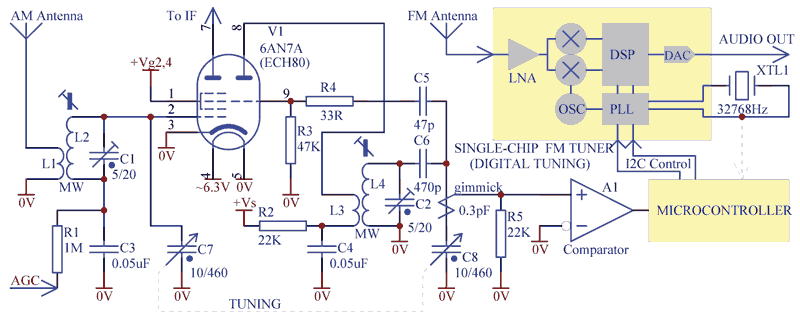
Fig. 1. Tuning of a FM receiver by microcontroller based frequency counter.
The example in Fig. 1 is based on a typical triode-hexode frequency changer (frequency converter) of an AM radio. A small "gimmick" capacitor picks up the local oscillator voltage, which is converted into a square wave by a comparator A1. A microcontroller can do frequency counting and conversion into apropriate control signals for the FM tuner chip.
If a single-chip FM tuner accepts analog tuning voltage, then the circuit changes accordingly, as per Fig. 2.
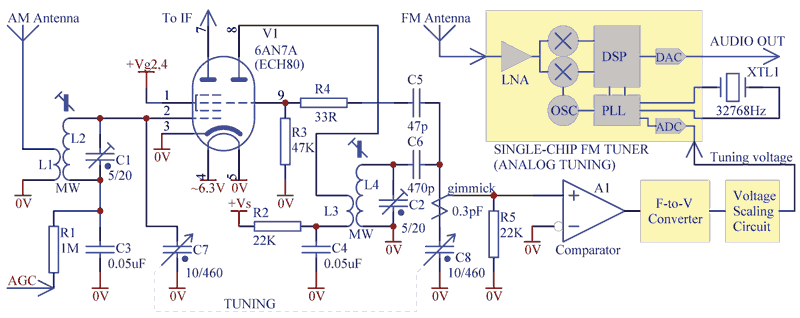
Fig. 2. Analog tuning of a single-chip FM receiver module.
Here a frequency-to-voltage converter is required, with some circuitry for scaling and linearisation of the tuning voltage, so that the tuning does become overly "crowded" at the high end of the band. The analog method may be not so precise and repeatable, but does not require microprocessor programming.
The "gimmick sniffer" mentioned above is a turn or two of an insulated wire around a wire to the oscillator section of a tuning gang capacitor (Fig. 3). Capacitance of the gimmick is a fraction of picofarad, so it does not appreciably affect aligning of the radio on AM bands. As the local oscillator amplitude is usually as high as 5...10V, such loose coupling is sufficient to drive a comparator.
FM tuner PCB module
The author of this article designed several variants of such FM tuners based on analog tuning. FA-3 and FA-4 (Fig. 3) are 30mm x 46mm size, FA-5 is larger -- 31mm x 52mm, based on the analog tuning, are described below. Mounting holes are 3.2mm, 39mm or 44mm apart respectively.
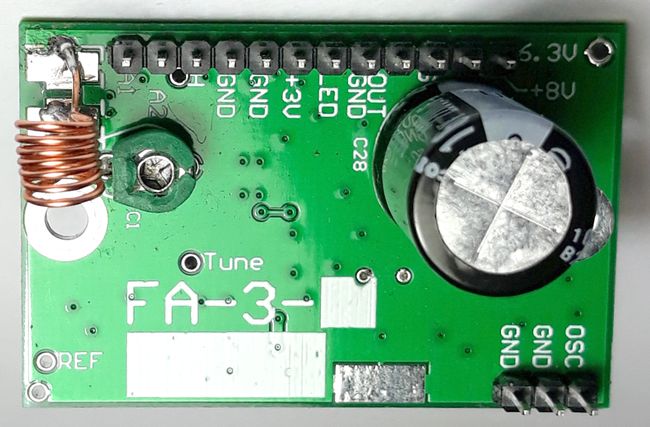
Fig. 3A. Top view of the FM tuner module PCB.

Fig. 3B. Bottom view of the FM tuner module PCB.
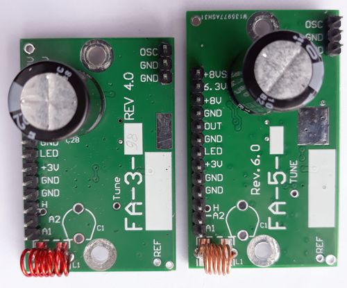
Fig. 3C. FA-3 and FA-5 (with connect auto-detect) modules side by side.
Basic connection of the modules is dead easy -- place on standoffs for grounding, power from ~6.3VAC (pin 12) from the heater winding, connect any (surrogate) antenna to pin 2 ("A2"), throw a "sniffer" gimmick to the oscillator section of a tuning gang and get about 1Vrms of audio at pin 9. (Alternatively, in a transistor radio, any 5...12Vdc 50mA supply can be used.) For better sensitivity, it has an additional RF amplifier based on a MOSFET tetrode. With 455kHz intermediate frequency, broadcast medium waves range frequencies from about 570...580kHz to 1500...1550kHz correspond to 87...108MHz of FM band.
Typical pinout of FA-3 and FA-4 and functions of the module terminals is presented in Fig. 4A, and pinout of FA-5 is shown in Fig. 4B.
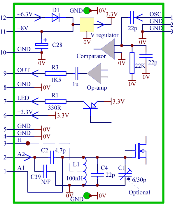
Fig. 4A. Simplified FA-4 pin configuration.
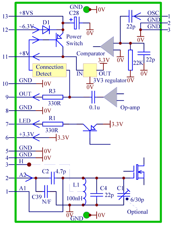
Fig. 4B. Simplified FA-5 pinout configuration.
Difference between FA-4 and FA-5 is that FA-5 has a special circuit for sensing of the load (that is a volume control potentiometer of 0.5...1MOhm) connection. When the volume control potentiometer is connected to pin 9, the FA-5 module powers up automatically, when pin 9 is open, the module powers down and will not create any potential cross-talk (leakage, bleeding) noise in the background of AM reception.
Pinout
Pin 1 ("A1") -- RF signal input directly connected to the antenna RF LC tank and the gate of the RF MOS-tetrode amplifier. Usually this pin is left unconnected, but might be useful for coupling of an external coaxial feeder, which will be explained below.
Pin 2 ("A2") -- Connection to a random wire or a telescopic antenna.
Pin 3 ("H") -- Connected only to a pad nearby and might be used as for convenience of arranging an inductive tap for coupling to a coaxial feeder.
Pin 6 ("+3V") -- 3.3V regulated voltage output. It can be used for powering some external user specific circuitry, provided current draw is below 10mA.
Pin 7 ("LED") -- Tuning indicator LED connection (sourcing current). The LED lights up upon once signal strength and signal-to-noise ratio exceed certain thresholds. It is driven through a pnp transistor switch and current limiting resistor R1 of 330R.
Pin 9 ("OUT") -- Audio output, about 1Vrms. (On request, can be increased up to 2.5Vrms for driving high transconductance output tubes, like EL33, directly.) The series resistor R3 (1K5 for FA-3, 4) allows shorting to ground without stressing the operational amplifier. In FA-5 this resistor is 330R for low output impedance; shorting is not needed due to automatic power-up / power-down function.
Pin 11 (+8V") -- In FA-3, 4 it is rectified (unregulated) supply voltage output. It is about 8.5V if the module is powered by 6.3Vac. This pin is usually unconnected, but can be used to power some user specific external circuitry with reasonably small current draw, or this pin can be used as power supply input of 5...12Vdc. 12VDC shall not be exceeded, as otherwise RF stage MOS-tetrode can be damaged. In FA-5 this is 8VDC internal rail which is activated when connection to pin 9 is detected, otherwise there is no power on pin 11. It can be used to drive "FM band" indication LED and/or some circuitry to shut down AM reception in FM mode, which will be explained later.
Pin 12 ("6.3V") -- 6.3Vac supply voltage input.
Pin 13 ("+8VS", in FA-5 only) -- Rectified (unregulated) supply voltage output. It is about 8.5V if the module is powered by 6.3Vac. This pin is usually unconnected, but also can be used as DC power supply input of 5...12Vdc. 12VDC shall not be exceeded, as otherwise RF stage MOS-tetrode can be damaged.
Pin 1 on the other side of the PCB ("OSC") -- Oscillator signal "sniffer" pickup (from a gimmick).
Other pins ("GND" or "G"), as well as mounting holes, are ground.
A generic way of connection of the module to an AM radio is illustrated by Fig. 5.
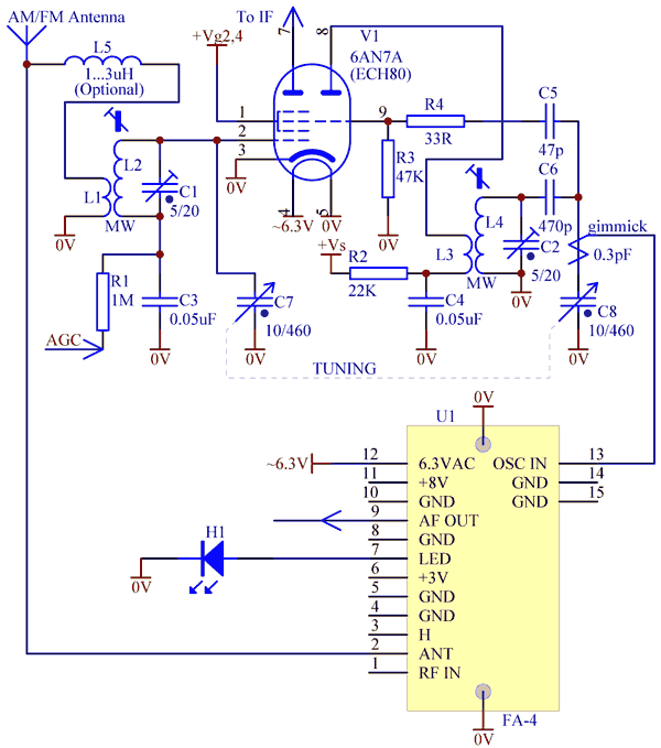
Fig. 5. Connection of the tuner module to a "typical" AM radio.
A random wire (0.1...1m long) or a telescopic rod antenna should be connected to pin 2 ("A2"). The same antenna terminal or post for AM antenna can be shared. A decoupling inductor L5 is optional, as usually the two signal paths do not mutually interfere anyway. Tuning indicator LED H1 is optional. If FA-5 module is used, another "FM band" indication LED can be connected to pin 11 through a 4K7...10K resistor. It will light up as soon as volume control is connected to the module. Fitted behind a dial glass, such LEDs would look great (Fig. 5B) and might further add to the perceived value of the radio.
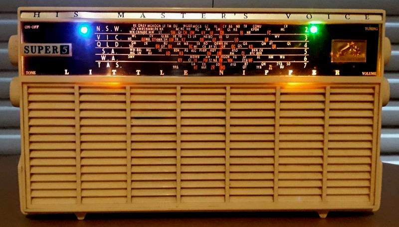
Fig. 5B. Indication LEDs ("FM band" -- blue, "TUNE" -- green) in a HMV "Super-5" Australian radio.
AM / FM switchover and cross-talk precautions
The simplest way to change between AM and FM reception is to fit a single pole double throw switch somewhere (most likely at the back of the radio) or possibly use a "RADIO / PICK-UP" switch on the front panel. However, there may be a potential cross-talk issue through stray capacitance of the switch and even in a first audio stage tube, as will be discussed further.
Needless to say, if you are prepared to sacrifice AM reception altogether, then choose a simpler FA-3 or FA-4, permanenty power it on, permanently connect to the volume control potentiometer, pull out an IF stage tube (to disable the AM reception and eliminate possible cross-talk) and optionally fit a 22K...33K resistor across the supply to make up for current draw reduction. Purpose of that will be elaborated upon below.
Impedance of the AM detector is rather high, so leakage from a FM module can easily penetrate through stray capacitance of the switch and be heard in the background. Therefore, the FM module in the AM mode shall be either powered down or its output shall be shorted to ground.
FA-5 powers down automatically once the volume control is disconnected, so a simple SPDT changeover switch is sufficient (Fig. 6).
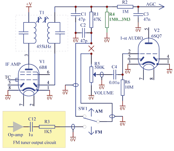
Fig. 6. AM/FM changeover example with FA-5 and detectors integrated with IF stage.
In AM mode the module will be powered OFF, and all the indication LEDs (if used) will be inactive, as expected. Added R4 prevents the AGC line from floating.
With FA-3/4, which is permanently ON, a DPDT switch is required to ground FM audio in AM mode (Fig. 7) to avoid cross-talk. Note R4 is switched in to replace detector load in FM mode.

Fig. 7. Cross-talk elimination with DPDT switch (detectors are integrated with the IF stage).
A drawback of this circuit is that the indication LEDs will always be active, even in AM mode, which is undesirable and confusing. Thus, this simple circuit is most suitable if there is no intention to fit any indication LEDs.
In FM mode, low output impedance of a tuner module would defeat any leakage through the switch stray capacitance, so apparently the AM section of the radio can be left working in FM mode without any cross-talk. That assumption is true only if the AM/AGC detectors are integrated with the IF stage pentode (e.g., 6B8, 6N8, etc.). In majority of the radios, however, AM/AGC diodes are integrated with the first audio stage (e.g., duo diode-triode 6Q7, 6SQ7, 6B6G, 6AV6, etc.). That opens up another path for cross-talk.
Due to physical proximity of the diode plate connections to the grid, on the tube socket or inside the tube, some IF voltage from these diodes (which may reach 10V at strong stations) may be induced on the triode grid through stray capacitance. Thus the triode might work as a parasitic grid-leak detector (or anode bend detector, depending on the bias method) and create an unpleasant cross-talk murmur. 6Q7 is the least susceptible due to the diodes enclosed in a shielding "box" and the grid connected to the top cap. 6AV6 tube is one of the worst. Though majority of them have a shielding box above the grid support rods, in some cheap variants (Fig. 8) grid support rods are literally sandwitched between the diode plates inviting for parasitic coupling.
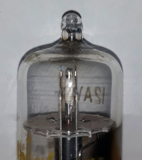
Fig. 8. Simple 12AV6 construction lacking grid shielding.
Therefore, if your radio has AM detector based on a duo-diode-triode tube, to be on the safer side, it is advisable in FM mode to mute the whole AM section of the radio. There are several ways of muting outlined below.
Fig. 9 illustrates how FA-3/4 module can be turned on/off by cutting 6.3VAC supply to it.
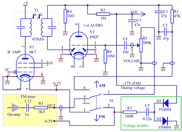
Fig. 9. Disabling FM tuner module by disconnecting its supply voltage.
When in FM mode 6.3VAC powers the module, a voltage doubler C5D1D2 sends about -17V to the AGC line, which almost completely mutes the AM section of the receiver. In AM mode, when the FA-3/4 module is powered down, all indication LEDs (if fitted) will be naturally OFF too. A drawback of this otherwise elegant method is reduction of current draw by the mixer and IF stages in FM mode. In old radios, where the output tube gets bias from the total supply current, that can result in exceeding its plate power dissipation rating. This is particularly dangerous if the radio has a speaker with a field coil.
A circuit in Fig. 10 is free from the above shortcoming. Here muting is achieved by removing of screen grid supply to the IF stage by shorting it to ground. (In some receivers, screen grid of the IF stage and a hexode mixer are joined together.) Importantly, resistor R8 creates additional 8...12mA current draw to maintain the overall current consumption about the same. Resistor R7 is not critical and prevents arcing on the switch closure when C5 is forced to discharge.
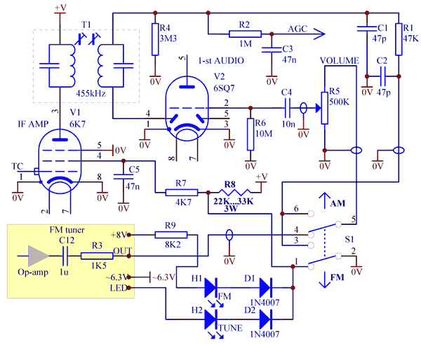
Fig. 10. Muting the AM radio in FM mode by shorting screen grid supply to ground by a switch.
The same switch which shorts screen grid supply to ground can be also employed to disable indication LEDs in AM mode. However, isolation diodes D1 and D2 are required. If FA-5 with automatic power on/off is used in this circuit, then, obviously, the isolation diodes are not required, and cathodes of both LEDs can be grounded.
Using FA-5 module with automatic shutdown is far more convenient in all cases. If only SPDT switch is available, for example "RADIO / PICK-UP" switch, then FA-5 is the only option. Fig. 11 shows how to implement muting in case of SPDT switch.
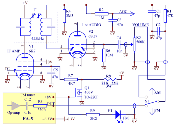
Fig. 11. Muting the AM radio in FM mode by shorting screen grid supply to ground by a MOSFET.
In this circuit muting is done by shorting the IF screen grid to ground, but by a MOSFET switch. Any n-MOSFET rated at 400V or more will be suitable, particularly in a convenient insulated TO-220 package, e.g., Toshiba TK4A50D. Alternatively, a suitably rated bipolar junction n-p-n transistor with a 4K7 resistor in series with its base can be used. For example, MJE340 is popular, but it is rated at 300V. Caution should be taken, as in some radios with directly heated rectifier tubes, on power-up, rectified voltage may exceed 300V and damage such transistor. Indication LEDs are naturally disabled when FA-5 module powers down in AM mode.
In all the above cases, instead of a separate switch, a tone control knob (if present in your radio) can be used to change between AM and FM. A switched potentiometer can be installed and wired so that its most anti-clockwise position corresponds to the full audio bandwidth. A switch of this potentiometer will control an electromechanical relay, which in turn will be switching over from AM to FM in any appropriate configuration as discussed above. De-energised position of the relay should correspond to FM mode, energised -- to AM mode. The relay (5V coil is recommended) should be of a signal, "telecom" type with silver or gold plated contacts, designed for reliable operation at low currents and voltages. Panasonic relay TQ2-2M-5V is suitable, as an example. A simple rectifier working of 6.3Vac can be arranged to power the relay, or it can be powered from the +8V output of the module (or "+8VS" in case of FA-5) via a suitable dropping resistor.
Thus, when the tone control knob is turned fully anti-clockwise past the "click", the relay would drop and the radio would switch to FM with full audio bandwidth. (There is no reason to cut off treble when listening to high quality sound from FM stations.) Turning the know clockwise past the "click" of the switch will energise the relay, switch to AM reception, and then, rotating the tone knob further, a listener will be able to "muffle" the treble, if needed, to make the sound "mellow" and/or reduce noise or "whistles".
Another elegant solution would be to fit a DPDT push-pull switched potentiometer (similar to the one shown in Fig. 12) as volume or tone control in the radio. A relay will not be needed and wiring can be made compact.
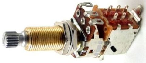
Fig. 12. A potentiometer with a push-pull DPDT switch.
Fitting such a potentiometer will not be straightforward though, as most likely the shaft will have to be extended to couple to the existing knob.
In conclusion, as shown above, FA-5 with the connection auto detection is far more convenient to use in all cases.
Coupling to FM antenna
A telescopic FM aerial probably is the best, but would look really out of place on a vintage radio. The simplest acceptable solution is to place a piece of wire and attach it to the inner top surface of the timber, bakelite or plastic cabinet of the radio or thread through the holes of the back board. It is quite sufficient for clear reception of the local FM stations, as the module is quite sensitive with its RF preamplifier. Alternatively, FM antenna input of the FM tuner module can be connected in parallel to the AM antenna terminal (Fig. 5), and the same (long wire) antenna will work on both bands. In these cases the antenna is coupled to the front end LC tank through a small (4.7pF) capacitor. A decoupling inductor L5 is optional, as usually the two signal paths do not mutually interfere anyway. Note that a long wire antenna, which is good for AM, may not be the best for FM, as it may be prone to multi-path reception. Thus, if a decent AM antenna is expected to be used with this radio, a separate FM antenna would be preferred.
For the ultimate performance, if an outdoor antenna is to be used, a matched 75 Ohm coaxial feeder can be connected to a tap in the front end LC tank.
To arrange a "capacitive tap" (Fig. 13), internal capacitor C4 on the nodule PCB shall be carefully removed. External capacitors C4 and C1 (Fig. 8) will provide an adequate impedance matching.
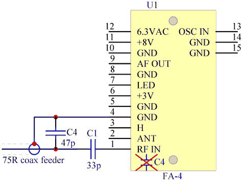
Fig. 13. Capacitive coupling/matching of an unbalanced 75 Ohm coaxial feeder to FM module.
Alternatively to Fig. 13, the coaxial cable can be connected to pin 2 ("A2"), but a surface mounted 0603 sized capacitor C39 = 47pF...56pF shall be fitted to the PCB, and C2 on the PCB changed from 4.7pF to 33pF...39pF.
It might be easier to arrange an inductive tap instead as shown in Fig. 14.
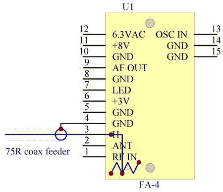
Fig. 14. Inductive coupling to the front end through a tap.
In this case, the top of the third (counting from the grounded left hand side) turn of the coil L1 shall be carefully stripped of the enamel insulation, tinned, and a wire tap soldered to it. For convenience, a pad close to pin 3 ("H") can be used (Fig. 14A).
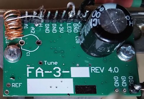
Fig. 14A. Connection of the antenna to a 30...50% tap of the coil, using "H" pad and pin 3 of the pin strip.
In general, connection to pin "A2" is recommended for a short (10...30cm long) surrogate antenna, while an inductive or capacitive tap is better for a decent telescopic rod (50...80cm long) antenna or for a coaxial feed.
Finally, in case of a balanced 150...300 Ohm feeder (ribbon "noodles" cable) a three-turn coupling coil can be wound around the existing 6-turns inductor L1.
Note that tuning of the front end LC tank to the middle FM band frequency 100MHz can be done by stretching/compressing the turns of the coil L1 or by the optional trimer capacitor C1 (if fitted). Practically, fine tuning is not really necessary, but for the absolute best sensitivity, the coil can be either compressed (to increase inductance) or spread out (to decrease inductance), or the trimer capacitor (if fitted) adjusted. To fine tune, find a weak station in the middle of the band, and, by adjusting the coil or the trimcap, try to achieve reception with minimum static noise.
Mounting of the FM tuner module
Because of a relatively small size of the module, it is always possible to mount it somewhere next to the tuning gang variable capacitor of an AM radio. Obviously, oscillator signal pick-up wire should run clear of AC circuitry. The module should not be placed close to the power transformer. Some examples of the installation and the "gimmick" are shown in the below pictures.
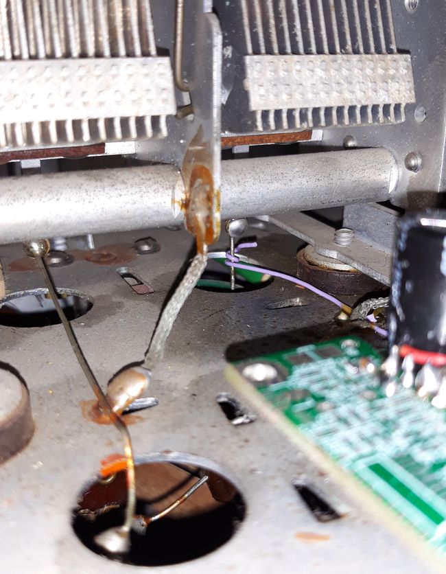
Fig. 15A. "Gimmick" coupling to the oscillator section of the tuning variable capacitor (Australian His Master's Voice radio, model 42-71).
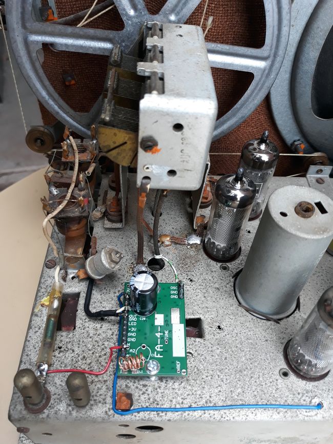
Fig. 15B. FA-4 FM tuner module fitted into an Australian Philips model 125 vintage radio. Gimmick is the white/green striped wire. Antenna post is shared. A decoulping (though practically useless) inductor can be seen on the left, in a clear plastic tube.
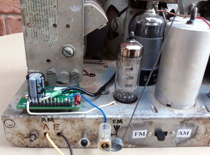
Fig. 15C. FA-4 module and AM/FM slide switch fitted to Scharnberg-Strauss 4-valve radio, model 41. A separate FM antenna terminal is provided with a surrogate antenna (piece of wire) attached.
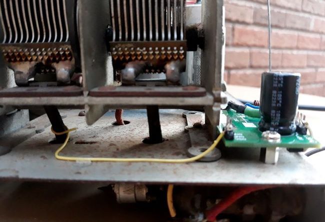
Fig. 15D. Oscillator signal pick-up gimmick in the Scharnberg-Strauss radio.
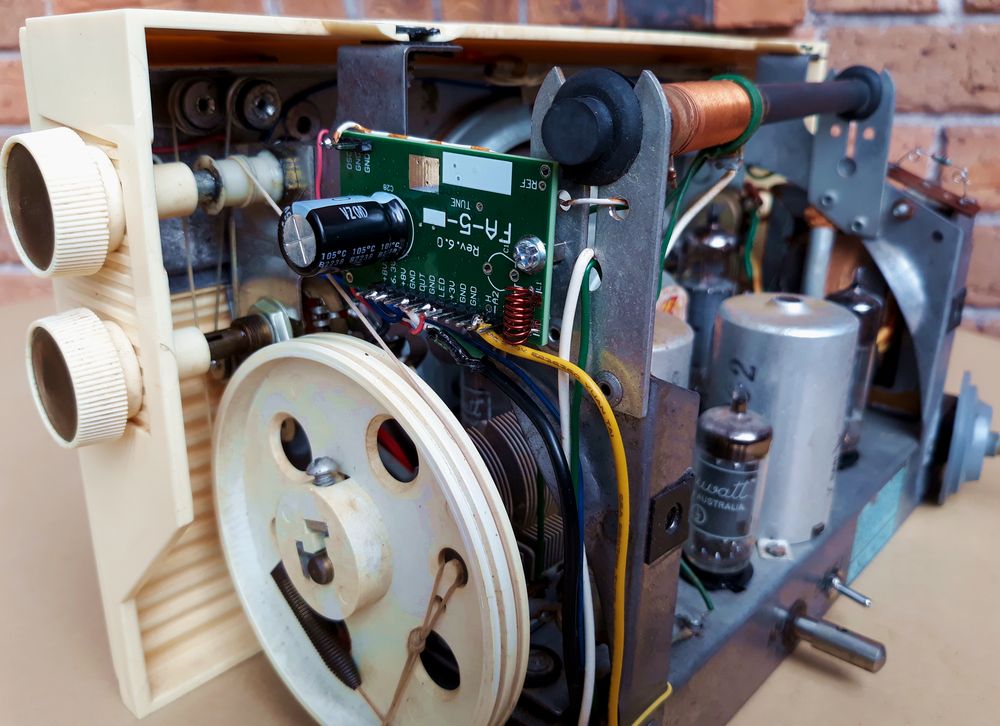
Fig. 15E. FM tuner module FA-5 in His Master's Voice model 65 ("Super-5") radio, mounted on the ferrite rod antenna frame. AM/FM band switch and FM antenna post are fitted at the back of the chassis.
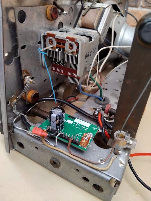
Fig. 15F. FA-3 module in a Kriesler (model 11-81) radio. Inductive tap is used for coupling. A screw terminal is fitted for FM antenna.
Practical schematic diagrams
Below are schematic diagrams (click on them to view full size) of conversion of some Australian AM radios to FM reception.
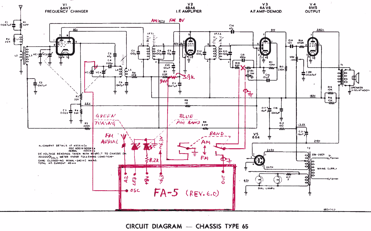
Fig. 16A. Connection of FA-5 to a HMV "Super-5" (model 65) radio. As the first audio stage is integrated with AM detector, it is preferable to mute AM chain in FM mode. It is achieved by shorting screen grid voltage of the IF stage.
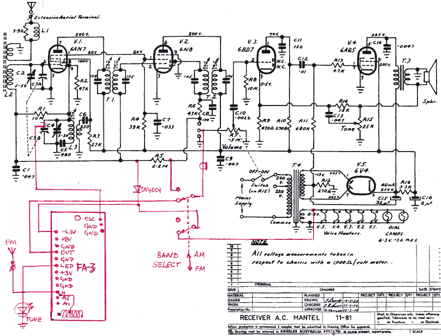
Fig. 16B. Connection of FA-3 to Kriesler model 11-81 radio. FM antenna is coupled by a tap to the coil. Enabling of the FA-3 is done simply by supplying ~6.3V in the FM mode. As the first audio stage is free from AM detector, muting of the AM chain in FM mode is not necessary, however, just in case, a partial muting is achieved by 1N4004 diode, which sends about --8V to the AGC, significantly reducing AM sensitivity. This diode is optional and not necessary.
For all enquiries -- technical or about availability for purchase -- do not hesitate to use the contact page of this website.

