Original circuit
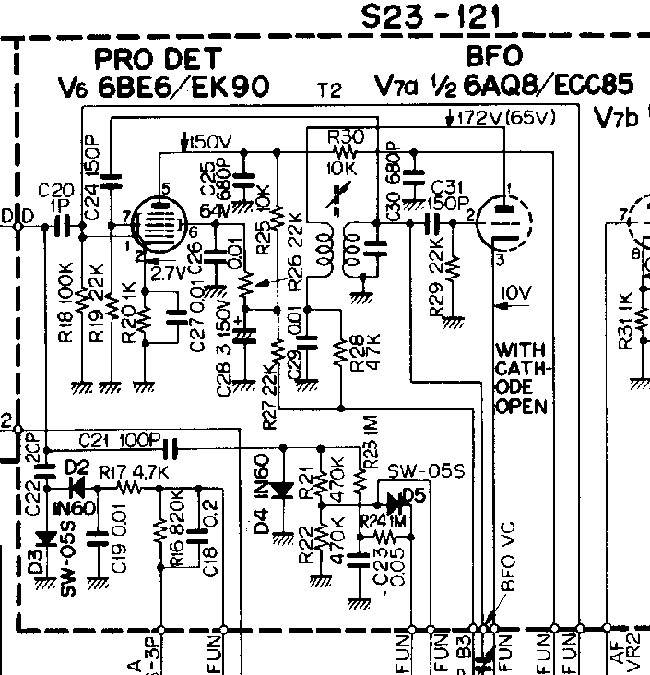
9R-59DS communications receiver already has got relatively advanced product detector using 6BE6 heptode and a separate BFO oscillator (Fig. 1).

Fig.1. SSB product detector in 9R-59DS
Though it might not be as good as a balanced diode ring detector, it is still much better than a crude BFO injection into an AM envelope detector.
The circuit has a shortcoming though. IF signal is fed to grid 1 (inner grid) of the heptode, and BFO is connected to grid 3 (outer grid). IF signal modulates the electron flow through the tube and thus modulates space charge (cloud of electrons) under grid 3. From grid 3 this pulsating charge gets injected into BFO oscillator tank T2. Such effect is called space charge coupling and is equivalent to a virtual negative capacitor of about --0.5pF between grids 1 and 3. All dual control tubes (special pentodes, hexodes, heptodes, etc.) are subject to such effect. In the opposite direction -- from the outer grid to the inner grid -- the charge coupling is much smaller, almost negligible (except for tubes 6A7 and 6A8 where the coupling is terrible in both directions). Virtual injection of IF signal into BFO tank tends to lock it onto the IF signal, pull in or destabilise frequency. As a result, CW and SSB reception becomes distorted, rough. When zero-beat tuning into AM stations, by nature of such charge coupling the BFO tends to lock 90 degrees out of phase with the carrier, thus defeating synchronous AM demodulation. (As well known, for synchronous AM reception the injected carrier shall be in phase with the original carrier.)
Modification
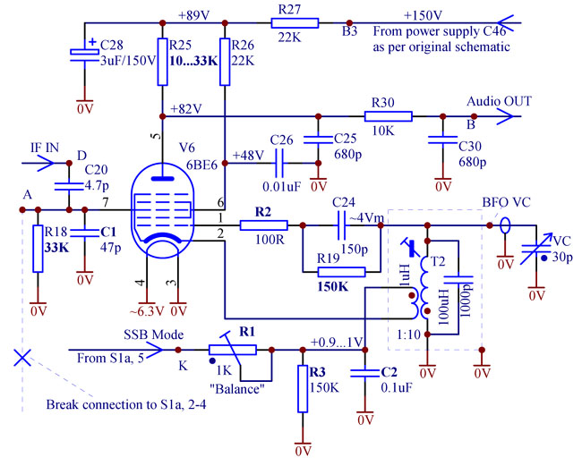
A simple modification can greatly improve the SSB product detector in 9R-59DS radio. A circuit is presented below (Fig.2.) Full schematic of the receiver can be downloaded here.

Fig. 2. Improved self-oscillating SSB product detector in 9R-59DS
Signal and oscillator grids are swapped to avoid charge coupling effect. Besides the pentagrid is configured to work as a self-oscillating BFO, as 6BE6 is commonly used. In fact, oscillation amplitude becomes larger than in the original design with ECC85 as a separate oscillator.
Many circuit components (V6, R25, R26, R27, R30, C24, C25, C26, C28, C30, T2) may remain unchanged. Some are removed: R20, R28, R29, C27, C29, C31), others (marked in bold in Fig. 2) -- modified. New parts (C1, C2, R1, R2, R3) are added. R18 is reduced to have less noise and hum. Grid-stopper R2 is recommended, R19 is connected in a way to reduce loading on the lank T2. Less loading results in better frequency stability.
Phasing of T2 is important. The terminal which used to be connected to R28,C29 is now connected to V6 cathode, and the terminal which was connected to V7a plate, is now connected to R1, R3, C2. When SSB mode is OFF and R1 is disconnected from ground, the "bleeder" resistor R3 prevents cathode potential from rising to dangerous levels in case of leakage in the tube. At the same time this current through R3 is too small to get V6 working in AM mode. Thus grounding of the IF input to the product detector in AM mode is redundant and the long wire to the switch S1a, pins 2, 3, 4 should be disconnected and removed from the radio to minimise noise pick-up.
Capacitor C2 shall be stable of good quality, e.g., polyester film, rated at 100...250V. Its quite large value 0.1uF is optimised to compensate leakage inductance between the main and tickle windings in the transformer T2.
Trimmer potentiometer R1 "Balance" controls negative bias at grid 3. With an optimum bias suppression of unwanted direct AM demodulation is the best. If bias is zero, then grid 3 will work like a grid detector -- increasing IF amplitude will result in reduction of plate current. If negative bias is too high, then the tube (or rather top part of it, grids 3, 4, 5) will be biased close to cut-off onto the steep "bend" in the curve and will work like an anode bend detector -- rising IF amplitude results in increasing of the plate current. At a certain bias in between these two extremes, these two opposing modes of AM detection would cancel each other out, providing the cleanest SSB reception.
To perform "balancing", the receiver should be tuned into a strong AM station and switched to SSB mode. BFO should be temporarily significantly detuned to get very high pitched "monkey chatter" (turning the slug of T2 will be required). Then R1 is adjusted to get direct AM demodulation of the programme as soft as possible. Ideally only the screech of sidebands should be heard, not the sound of the audio programme itself. Note that during this procedure the volume control ("AF gain") should be as low as practical, otherwise the high-pitch screech may be directly demodulated in the audio amplifier which is not very linear. When R1 adjustment is finished, the slug should be tuned back to its normal position, so that BFO tunes to 455kHz in the middle position of BFO pitch control on the front panel.
Because of subtle variation in linearity features of different samples of 6BE6, it is recommended to readjust after changing the valve. Selecting the tube, choose the least microphonic one.
Implementation of modifications
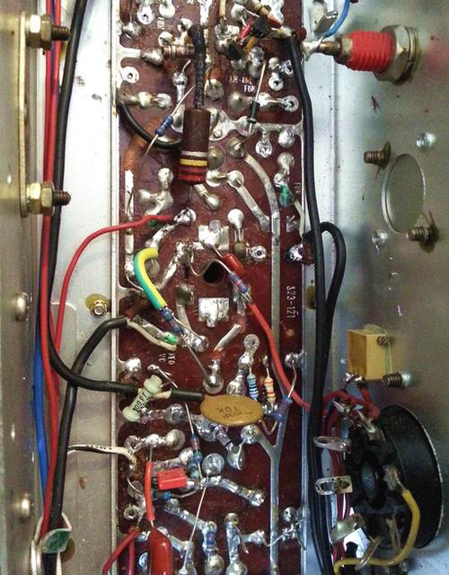
As shown in Fig. 3, components may be soldered underneath the chassis directly to PCB tracks without drilling through the PCB.

Fig. 3. View of the modified PCB
Some PCB tracks will have to be cut. When swapping pins 1 and 7 of V6, leave wide gaps in cut or ground away tracks to minimise capacitive coupling between IF signal and BFO. Multiturn trimmer R1 (yellow part in Fig. 3) can be glued to the wall of the chassis.
The described modification frees up tube V7 from any IF function, and it can be fully dedicated to audio. This opens ways for modification of the audio amplifier, for example, introducing negative feedback for better sound quality. For that purpose, V7 can be changed to 12AX7. Higher amplification factor will allow for a deeper feedback. Such audio stage modifications, as well as some changes to AM detector circuitry, can be seen in Fig. 3, but not described in this article.
