Electrosound Radio with SSB detector

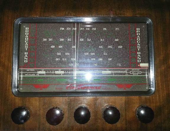
This radio was made in Australia probably around 1950. It is a large receiver 560 x 380 x 295 mm in size, in a robust solidly built timber cabinet, with a powerful 8-inch speaker.

The radio has three bands:
- Broadcast medium wave band, 540...1650 kHz;
- Shortwave low "tropical" band, 2.5...7.5 MHz (120...40 m);
- Shortwave high band, 7.5...22 MHz (40...13 m).
Control knobs are (left to right): Tone, Volume/ON/OFF, BFO ON/OFF (AM/SSB), Tuning, Band switch.

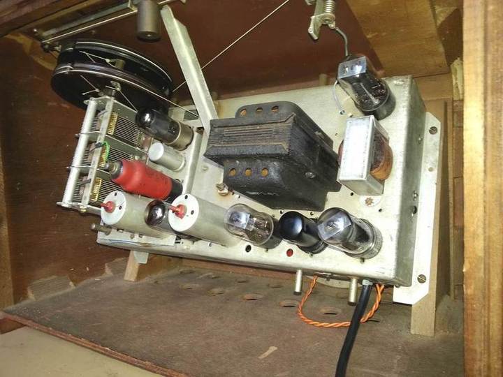
It is a 7-valve radio with a unique feature -- beat frequency oscillator and a product detector for listening to Morse code (CW) or single side band (SSB) transmissions. Tube line-up is as follows: 6SK7 (RF), ECH35 (Local oscillator and mixer), 6SK7 (IF), 6SQ7 (AM detector, AGC detector, first audio stage), 6SA7 (Beat frequency oscillator and product detector), 6V6GT (Output audio), 5Y3GT (Rectifier). Circuit design is straightforward.
A quality triode-hexode ECH35 (red coated tube) is used which has high conversion transconductance (hence lower noise). It works with self-bias, and AGC voltage is not applied to it on shortwave bands, similarly to what described in another article. This improves frequency stability -- tuning or the radio does not drift or "swing" with the signal strength changing.
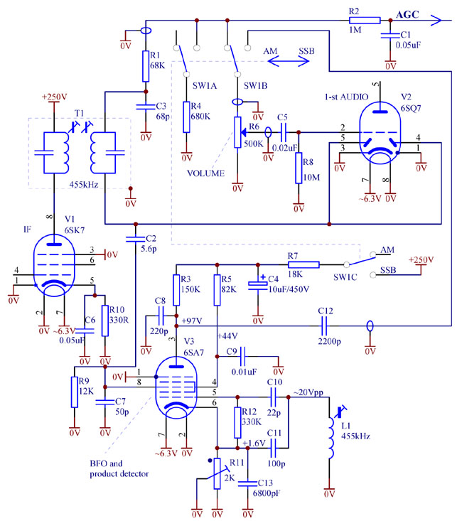
BFO and product detector schematic is shown below.

IF signal is fed to the product detector via C2. To avoid overloading and direct demodulation, the signal is attenuated by 20dB through capacitive divider C2C7. Relatively low value of R9 prevents audio components from the IF transformer T1 from directly entering and being amplified by pentagrid V3. Filter R7C4 removes ripple from the supply voltage thus eliminating hum in SSB mode. Relatively small value of interstage audio couplling C12 cuts low audio frequencies, and voice sounds better. Besides it helps prevent motorboating.
In AM mode, volume control potentiometer R6 serves as a load for the AM detector. In SSB mode, for correct operation of AGC, this load is substituted by R4.
Screen grids 2 and 4 of the pentagrid are not decoupled at audio frequencies. This increases the gain of the product detector. For example, suppose that at some point in time, signal grid 3 is out of phase with grid 1, and plate current tends to reduce. It means that screen grid current has to increase by the same amount because of redistribution of cathode current. However, since screen grids are not bypassed at audio frequencies, screen voltage lowers, which causes the cathode current to lower as well, further reducing plate current.
With its two shortwave bands, this radio covers amateur bands of 80m (3.5MHz), 40m (7MHz), 20m (14MHz) and even 15m (21MHz). On the low bands, 80m and 40m, ham operators use low side band, on the high bands -- upper side band. Because the local oscillator runs above the signal frequency, side bands get inverted at IF -- upper on low bands, lower -- on high bands.
Therefore, to obtain some suppression of an unwanted side band, it is better to tune the BFO (L1) to the low slope of the IF passband for 80 and 40m, and to the upper slope of IF passband for 20 and 15m. Given that tuning accuracy and stability may not be sufficient for 20 and 15m, it is recommended to use this receiver for casual listening on 40m and 80m and consequently to tune the BFO slug to the lower slope of IF passband. You can view a demonstration here.
If listening to both upper and lower sidebands is required, then as a matter of a tradeoff, the BFO can be tuned to the middle of the passband (to nominal 455kHz). In this case there will be no suppression of unwanted sidebands.
Trimmer R11 is used to minimise direct AM detection by the product detector. This phenomenon utilises S-shaped control characteristics of grid 3. R11 virtually changes negative bias on grid 3. It is known that with low negative bias, increase of IF signal at grid 3 would cause plate current to reduce, like in a grid-leak detector. If the negative bias is high, and the grid 3 is closer to cut-off, then increase of IF at grid 3 would result in the plate current rising, like in an anode bend detector. Obviously, at some bias value these two non-linearities cancel each other in the first order approximation.
Therefore to "balance" the product detector for the best sound quality, it is recommended to:
- tune into a strong station which would produce large IF voltage at grid 3 of the pentagrid V3;
- detune BFO (L1) away from the IF frequency to make the beat frequencies high and inaudible;
- adjust R11 to get the sound resulting from the direct demodulation as soft as possible, almost inaudible;
- then tune L1 back within the IF passband, slightly off centre, depending on which sideband is desired, as explained above.
Adjustment of R11 is not critical. It might be done after changing the 6SA7 valve. If several samples of 6SA7 are available, it is advised to choose the least microphonic one. In this respect metal 6SA7 are better than their glass siblings 6SA7GT.
