1. Drawbacks of the original design of Lafayette HE-30 / KT-320
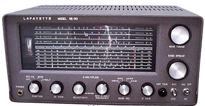
Lafayette HE-30 (similar to Trio 9R-59) and its kit version KT-320 is a basic single conversion tube semi-professional short wave communications receiver. More about this receiver can be found in another article.

As many other similar designs, it has one RF stage (6BA6), local oscillator (6BE6 in triode), mixer (6BE6), two IF stages (6BA6), AM detector and first audio (6AV6), output audio (6AQ5), rectifier (5CG4). This model also has a Q-multiplier (6AV6) which can work as a BFO if driven into continuous oscillation. BFO signal is injected into the 1-st IF input via stray coupling.
You can download original HE-30 schematic here.
You can download full HE-30 operating manual here.
Original HE-30 receiver has several drawbacks. To name a few, it has less than desired frequency stability at the top band, low audio quality, poor SSB reception and almost useless Q-multiplier.
Using the Q-multiplier for shortwave AM listening serves no purpose as the IF bandwidth of the radio is already quite narrow (4kHz).
In the SSB mode, the Q-multiplier is biased into self-oscillating mode and its signal is injected (through a stray capacitance) to the first IF transformer. As a result, a large AGC voltage is developed on the AM detector which desensitizes the receiver. (One can use manual gain control though.)
Another problem is when one attempts to place the BFO frequency on a slope of the IF curve to get a true SSB reception, the BFO signal gets attenuated, because the IF gain is smaller on the slope. Thus the BFO signal becomes insufficient and strong interference may drown a signal of interest by crude direct AM detection. Attempts to reduce RF gain do not help, as this also reduces the IF gain and makes the BFO level even smaller.
The above drawbacks make the HE-30 / KT-320 receiver very inconvenient for SSB listening.
2. Product SSB detector
To overcome the above mentioned deficiencies of an injected BFO approach, in the later models a dedicated SSB product detector using a heptode (pentagrid) appeared. A representative example is Trio/Kenwood 9R-59DS receiver.
You can download original 9R-59DS schematic here.
You can download full 9R-59DS operating manual here.
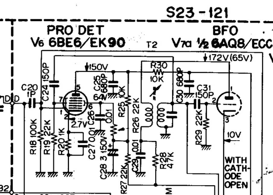
Below is a fragment of the 9R-59DS circuit of the product detector.

Fig. 1. Product SSB detector in 9R-59DS receiver.
It uses a heptode (pentagrid) V6 6BE6 and a separate BFO oscillator. It might be tempting to fit a similar circuit in HE-30, but such direct "copy-and-paste" is not practical for the following reasons:
a) These are no spare tube sockets in HE-30 to add the product mixer and the BFO;
b) There is no spare wafer on the mode switch to switch audio path from either AM detector or the SSB detector to volume control;
c) The IF signal is fed to the first grid of the heptode (pentagrid), and the BFO -- to the third grid. Because of the space-charge coupling, the BFO might be pulled by strong signals. This is particularly noticeable when listening to strong AM stations in SSB mode. Close to zero beats the sound becomes coarse and unpleasant.
Therefore, a different solution is needed for implementing a product SSB detector in HE-30.
2. Fitting a product SSB detector into a HE-30 receiver
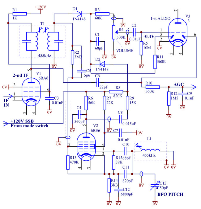
A schematic diagram of the modifications required to add a product SSB detector to HE-30 / KT-320 receiver is shown in the picture below.

Fig. 2. Product SSB detector in HE-30 receiver.
Let us discuss the main features of the circuit.
a) Separate AM detector and AGC detector.
In the original HE-30, AGC is derived from the main AM detector. Thus the AM detector gets "AC burdened" by the AGC filter and can not handle more than 70% modulation. In the proposed circuit, the detectors are separate which allows the main AM detector to handle deep modulation.
b) Forward bias of the AM detector diode.
As can be seen, a silicon diode D1 is used in the AM detector. An unusual feature is that the diode is lightly forward biased to the "kink" by a negative voltage generated by thermionic electron emission in one of the diodes of V3, 6AV6. Forward vias voltage is about 0.3V. It is a custom belief that the "kink" of a silicon diode is 0.6..0.7V. However, at minuscule nanoampere range currents conduction actually begins at low voltages, 0.25...0.4V, especially when the radio is warmed up. Thus the 0.3V bias is near optimum and the small-signal sensitivity becomes better than of a vacuum diode. The detector works directly into the volume control and not burdened by parallel loads. Resistor R3 together with capacitance of the shielded cable filters the IF residual ripple.
c) Heptode (pentagrid) product SSB detector.
Here the heptode V2 works with the oscillator voltage applied to grid 1, and the IF signal -- to grid 3. Such topology is much better in terms of reducing parasitic coupling between the IF and BFO. In a heptode 6BE6, backward space-charge coupling from grid 3 to grid 1 is almost non-existent, thus the BFO is not synchronised (pulled) by the IF signal. (As a side note, old pentagrids 6A7 and 6A8 are much worse than 6BE6 and 6SA7 in this respect and have notoriously bad space-charge coupling in both directions.)
The circuit uses capacitive coupling to the BFO LC tank, as opposed to inductive coupling commonly found in frequency changers of the radios. IF signal is applied to grid 3, through a capacitive divider comprising C5 and the shielded cable capacitance. The divider reduces the IF AC signal on grid 3 to under 100mV to avoid overloading and distortion. Also it helps make the overall gain of the product detector about unity -- so that volume of the radio does not change much when switching from AM to SSB mode. Resistive divider R13R2 produces optimum negative bias on grid 3 with respect to cathode to set the grid 3 operation point to the linear region and minimise quadratic direct AM rectification.
Note that C7 is relatively small, and screen grids 2 and 4 are coupled to ground at IF, but not at audio frequencies. This trick actually increases the effective conversion transconductance. Why it is so -- let the reader find out. C4 filters out residual BFO and IF ripple.
d) Electronic switching between AM and SSB modes.
As was mentioned earlier, HE-30 does not offer a spare wafer on the mode switch to be used in the audio path. So switching into SSB mode is done by applying "+120V SSB" from power supply rail of the receiver.
In AM mode, this voltage "+120V SSB" is disconnected and floating. Heptode V2 is dormant. Thermionic electron emission in V2 charges grids 2, 4 and the plate slightly negatively, which, through R8, reverse biases the switching diode D2, and the product detector gets virtually completely decoupled from the AM detector (which develops positive voltage further reverse biasing D2).
To switch to SSB mode, +120V DC or so is connected to "+120V SSB" line. Heptode V2 powers up and starts to oscillate. Product detector comes to life. At the same time, current through R8 forward biases D2, which dynamic resistance drops to a hundred ohms, effectively connecting the product detector to the volume control through C8R9. At the same time, this current creates about +40V DC on R3, R4, reliably reverse biasing the AM detector diode D1, even for the strongest signals. Thus the AM detector gets completely disabled, and SSB detector enabled.
A drawback of such electronic switching is a possibility of crackling when turning the volume control rapidly, because there exists a large DC voltage across it. However it is non issue if the volume control potentiometer is clean and not worn out. On the other hand, electronic diode switching has an advantage that there is no risk of intermittent contact, which may occur if low level, high impedance audio signals are switched conventionally by mechanical switches, if the later get oxidated.
Components V2, R6, R7, R13, R14, R15, C4, C7, C10, C11, C12 should be mounted in the same metal compartment where originally the Q-multiplier used to reside. C10, C11 and C12 must be mica or NPO (COG) temperature stable capacitors. Other components can be mounted closer to the third IF transformer and 6AV6 tube socket. The cables shown shielded, must be shielded. R2, C5 should have short leads.
Pentagrids 6BE6 were not generally designed for audio applications, and some, especially old cheap mass-produced tubes can be microphonic. Tube selection on test may be needed.
It is recommended also to regulate supply voltage to the local oscillator and the BFO, as described here.
Similar approach to adding a product SSB detector may apply to older communication receivers with octal valves. In this case, the mixer tubes with the first grid as oscillator grid should be used, like pentagrid 6SA7 or triode-hexode 6K8. Old 6A8 shall be avoided as it suffers badly from space-charge coupling.
