Converter frequency stability
Many of the old valve radios have shortwave band(s). Usually the first stage is a frequency converter using a multigrid tube: heptode, pentagrid, triode-hexode, triode-heptode, octode, etc. Those tubes are noisy -- equivalent noise resistance referred to the signal grid is 50...150KOhm, which limits sensitivity on short wave bands, when the impedance of the RF signal LC tank becomes lower than the equivalent noise resistance of the converter.
Another common problem -- low frequency stability. Not only frequency drifts with changes of temperature, supply voltage and heater voltage, but also with changing automatic gain control (AGC) voltage. On high frequency bands (13, 16 and 19m) this drift can become so pronounced (more than 5KHz) that on a fading shortwave station a receiver would be tuning in and out of the station, which degrades reception quality.
The worst converter tube in this respect is 6A7 or 6A8. A typical generic front end converter circuit is shown in Fig.1.
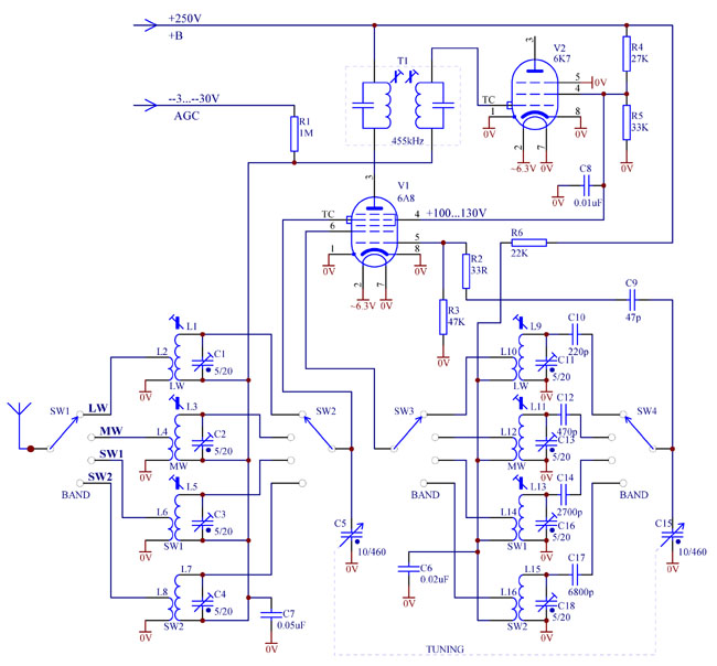
Fig. 1. Typical frequency converter using pentagrid 6A8.
In this tube, 6A8, local oscillator (LO) runs on a virtual triode, grid 2 (actually two metal rods) being its plate. When negative AGC voltage increases, reducing conversion transconductance, signal grid 4 starts repelling more electrons, sending them back -- towards screen grid 3. However, many of these returning electrons are not intercepted by grid 3, but travel further towards cathode to positively charged rods of grid 2 (oscillator plate). Some of these electrons got caught by the rods, thus increasing oscillator plate current.
Therefore, in 6A8 increasing AGC causes rise of the oscillator transconductance, which inevitably affects frequency. Also, since the returned electrons come to grid 2 with a longer delay than those which arrive straight from the cathode, this propagation delay pulls the frequency down. Some electrons manage to make several trips back to negative grid 1 and forth to grid 4, until caught by some positive grid on the way. Such unprofitable "traffic" contributes to so called space charge build up near negative grids -- above grid 1 and under grid 4. Such space charge adds to frequency instability and causes parasitic coupling between the LO and signal LC tanks.
To improve frequency stability it is possible to use more advanced frequency changer tubes (triode-hexodes) with separate electron flow for oscillator and mixer sections. Such tubes are 6J8, 6K8, though they have smaller conversion transconductance (250...350uA/V), and the European series, for example ECH3, ECH35, ECH80 (6AN7A), ECH81. The later have high transconductance (600...750uA/V) and acceptable stability for AM listening.
For a demanding listener and for SSB applications this can be still insufficient. To further improve performance, three modifications are needed:
1) Not using AGC in the converter stage on short waves;
2) Regulation of screen grid and LO supply voltage;
3) Separating screen grid supply filters to prevent AGC operation in the IF stage affecting screen voltage in the mixer;
These simple modifications are shown in Fig. 2 below.
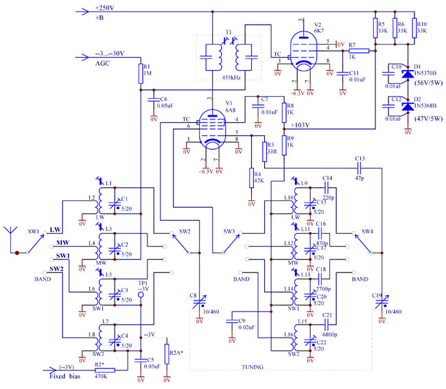
Fig. 2. Frequency converter with improved stability and fixed bias.
As can be seen from Fig. 2, the "cold" ends of the signal LC tanks are separated. On long and medium wave bands the mixer receives AGC via R1C6 filter, while on short waves fixed bias voltage is supplied through R2C5. Bias voltage must be free of ripple and preferably regulated. It can be taken from a bias resistor or a suitable Zener diode inserted in the "negative" leg of the power supply circuit, or from a dedicated regulated supply. Voltage should match recommended specification for a tube. For example, 6A8, 6K8 or 6K8 would need --3V, while ECH35, 6AN7A (ECH80), ECH81: --2V. Divider R2R2A can be used to obtain the desired bias voltage.
Supply voltage regulator Zeners D1 and D2 require special attention. Firstly, it is better to use two Zeners with total 100...105V voltage, rather than only one. It helps share power dissipation and have them running cooler. Secondly, Zeners are notorious for generating wide-band noise. To prevent it from propagating through the circuit and being picked up by sensitive stages of the receiver, each Zener shall be shunted by a low-inductance (e.g., disk ceramic) capacitor, soldered as close as practical to the Zener body. Capacitor's leads shall be kept as short as practical too. These measures reduce the "loop" inductance and help minimise radiation of magnetic noise, as well as minimising noise voltage across each of the Zeners.
Using one shunt capacitor for both Zeners is not acceptable, as the "loop" area will be significantly larger. Also do not attempt specifically to solder the filtering capacitors to chassis, but solder to the Zener's leads close to its body. Even after all the precautions are taken, it is better to place the Zeners in the power supply "section" of the chassis and away from the sensitive nodes -- RF input, antenna circuit, first IF grid.
An example of Zener bypassing by a disk ceramic capacitor is shown in a photo below.
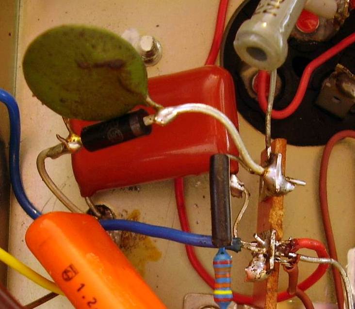
Fig. 3. Shunting a high voltage Zener by a disk ceramic capacitor.
Instead of fixed bias on the short waves, self bias (automatic bias) can be used, especially in the later models of vintage radios from the 50's. Self bias does not require a regulated negative voltage. The circuit can become simpler. An example of such circuit is shown below.
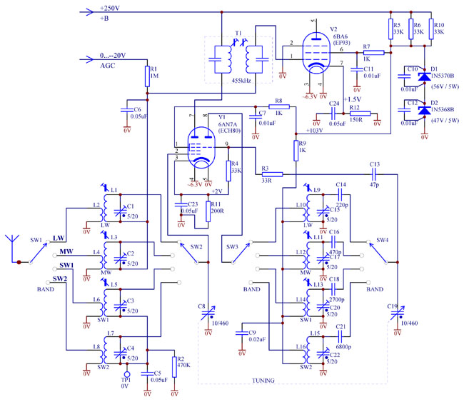
Fig. 4. Mixer with self bias.
In this case, AGC voltage starts from zero, not from --3V (or --2V) as in Fig. 1 or Fig. 2. For that reason, the IF stage also has self bias arrangement. Mixer triode-hexode tube 6AN7A (ECH80) is shown as an example, but any other will work too with appropriately chosen self bias resistor R11, for example, more popular ECH81.
Note that though DC potential of the RF LC tanks for the shortwave bands is zero, they are not directly grounded to chassis, but through a R2C5 filter. Such arrangement has several advantages explained below.
As commonly known, almost always there exists some parasitic coupling between the local oscillator LC tank and the RF LC tank. This coupling occurs through stray coupling between the coils, wiring and by the space charge within the mixer tube. If the outer grid is a signal grid (6A8, 6SA7, 6K8, EK2, EK3, etc.) it might be possible to compensate the coupling by a small capacitor, about 0.3pF, between the signal grid and oscillator grid of the mixer tube. However, if this coupling remains not fully compensated, then at high frequencies it causes a significant voltage to develop across the RF LC tank. If amplitude of this voltage exceeds the bias voltage, grid current in the signal grid 1 will start to flow. In this case input impedance of the signal grid will drop, the RF tank will get shunted, causing degradation of sensitivity and image rejection of the receiver and noise increasing. To avoid this effect, R2 is inserted. If a minuscule grid current occurs, it will develop additional negative voltage on the grid which might affect conversion transconductance, but will not degrade Q-factor of the RF tank and image rejection of the radio.
Test point TP1 can be used to monitor this grid current condition. If a multimeter connected to TP1 registers significant negative voltage (more than --0.5V), it means parasitic voltage induced on the RF tank is too high. It usually happens near the high frequency end of the dial.
To remedy this problem one might try to reduce local oscillator amplitude, adjust the small compensation capacitor mentioned above, attempt to put another compensation capacitor between the signal grid of hexode and the oscillator triode plate, swap the ends of the RF coil, install shielding between oscillator and RF coils, improve wiring, etc.
Oscillator stability of a receiver with RF stage
Simple single conversion "communications" receivers with an RF stage usually do not have AGC applied to the mixer. After the local oscillator (LO) and mixer screen grid supply voltages are regulated, oscillator frequency may still be affected by AGC operation, manual "RF/IF gain" control or even by "Antenna trim" adjustment. This effect is more pronounced on high bands. Why does it happen?
The answer is -- local oscillator injection into the mixer via signal path. At high frequencies, due to limited RF selectivity, local oscillator signal, if it leaks into the RF input, is not sufficiently suppressed. Thus it gets amplified by the RF stage together with the signal and gets injected into the mixer via signal grid. Then, through stray coupling or space-charge coupling between the signal and oscillator grids, it gets injected back into the local oscillator tank. Depending on the phase and amplitude of such back-injected signal, it pulls the oscillator frequency one way or another.
When AGC is working (or manual RF gain control is manipulated), RF stage gain is changing, back-injection strength is changing and consequently the amount of frequency pull is changing. Even turning "Antenna trim" capacitor changes the phase of the re-injected signal and affects the frequency pull. Thus the oscillator frequency drifts, which is annoying at least or unacceptable for a synchronous detector operation at worst.
How to remedy this phenomenon? Removing AGC from the RF stage on high bands is not recommended as it may result in overloading of the radio on strong stations. Better is to try to reduce back injection as much as possible.
Firstly, the shaft, sliding contacts and grounding straps of the multi-gang tuning capacitor shall be clean, corrosion free and well soldered. This will reduce LO leakage into the RF stage via common grounding impedance of the gang capacitor.
Secondly, RF input circuits shall be well clear of the LO circuitry. In some receivers, for example Trio/Kenwood 9R-59DS, a wire to the "Antenna trim" capacitor runs under the chassis close to the local oscillator components. Thus LO leaks into the antenna input circuit. Using a piece of a screened (coaxial) cable for that connection is not acceptable due to extra capacitance of the shielded cable. Better to run a flying wire above the chassis as shown in Fig. 5. It runs from the lug of "Bandspread" gang capacitor to the antenna trimmer under the chassis. The chassis and a shield on the oscillator tube ECC85 (left) reliably screen this connecting wire from LO radiation.
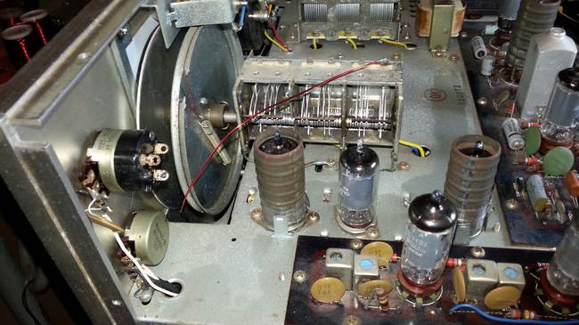
Fig. 5. Flying wire connection of the "Antenna trim" capacitor to RF antenna tank in Trio 9R-59DS receiver.
