Quality AM reception: Synchronous Detector versus Carrier Exaltation
A well known method of quality AM reception is a synchronous detector. By way of PLL, it generates its own carrier (in phase with the actual carrier of a radio station) and delivers audio signal by a linear product detector/multiplier. Apart from imminity to interference, a synchronous detector operates with minimum distortion under fading conditions. Even if a carrier of a radio station disappears from time to time, still "by momentum" its local oscillator continues to run at a frequency close to the carrier, keeping distortion-less reception until the carrier re-appears and PLL re-synchronises.
However, a synch detector is not the only way to enhance AM audio quality. An alternative method is called "Carrier Exaltation".
Carrier exaltation does not use a substitute carrier, but uses the natural carrier, but, through a special narrow-band filter, "magnifies" it several times, while keeping the sideband level the same. Fig. 1 illustrates an original AM signal spectrum (A), response of a special filter, which magnifies only the carrier (B), and the resultant spectrum of AM signal with thus reduced modulation index.

Fig. 1. Carrier exaltation by way of magnifying the carrier while keeping the side bands unaltered.
To achive the above result, the carrier can be selected by a narrow-band filter, amplified several times and combined with the input signal. Then the exalted AM signal is fed through a conventional AM envelope detector (Fig. 2).

Fig. 2. Simplified block diagram of a carrier exaltation AM detector.
The effective modulation index reduction, in turn, results in reduction of all sorts of distortion associated with imperfections of AM signal, including carrier fading, unbalance of the sidebands, interference, etc. For example, carrier "magnification" would allow more margin for the input carrier to fade until overmodulation at the envelope detector occurs.
Leaving aside technical issues of implementation of such narrow band filter, which shall also track the carrier and not shift the carrier phase, let us see how reduction of modulation index reduces distortion under different conditions.
Effect of carrier exaltation on distortion
Amplitude modulation, which has been serving mankind for more than a century, though simple and robust, is free from audio distortion only under ideal conditions, namely when: (a) amplitudes of the sidebands are equal; (b) sideband phases are symmetrical with respect to the carrier; (c) sum of the sideband amplitudes does not exceeed the carrier amplitude. If at least one of the above conditions is broken, distortion will ensue. The greater the extent to which they are violated, the higher the distortion will be.
Simulation plots below Fig. 3 - Fig. 8) illustrate how the lower modulation index reduces "severity" of the defects in the AM signal and reduces envelope distortion. The simulated AM signal has a 500kHz carrier and 1kHz modulation. On the left hand side of every plot, the carrier amplitude is 1V, each sideband is 0.5V, and on the right hand side half, after 3ms of simulation, the carrier amplitude gets "exalted" (amplified, magnified) four times (by +12dB, or from 1V to 4V), while all the other parameters of the signal remain unchanged.
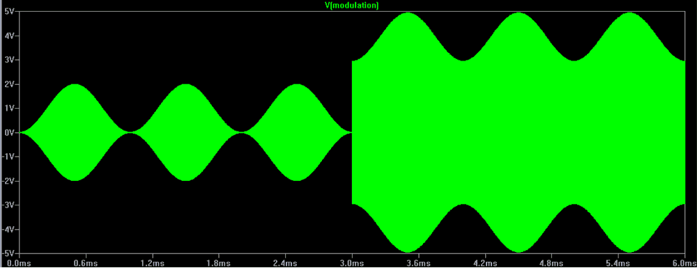
Fig. 3. Ideal AM -- 100% modulation.
In Fig. 3 the envelope is perfect in both cases, no distortion. With 12dB carrier exaltation, modulation index drops to 25%, and DC component at the detector output increases four times. Audio level remains unchanged.
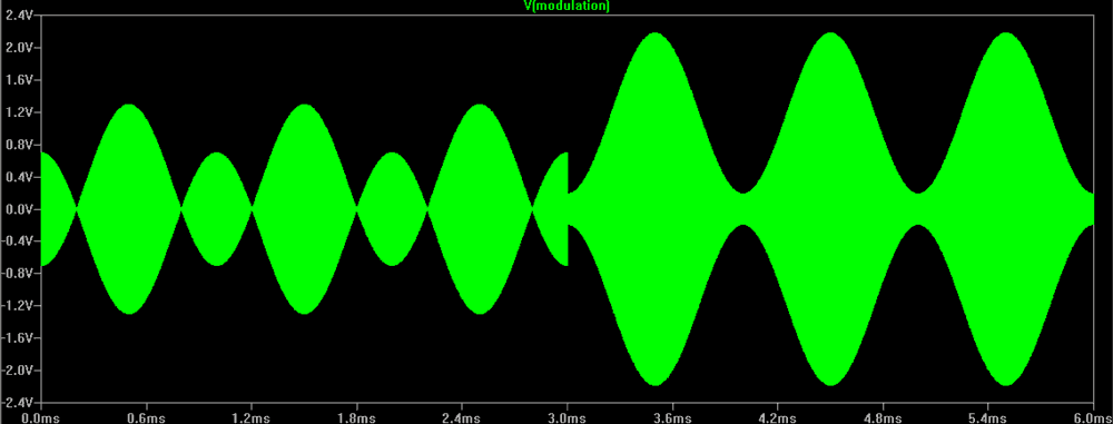
Fig. 4. Carrier reduced (faded) by 10dB to 300mV, sidebands are normal, 0.5V each.
Fig. 4 simulates a severe carrier fading. Carrier amplitude is reduces (on the left) by 10dB. Severe overmodulation is present with what looks like almost frequency doubling of the audio envelope. This is a typical annoying "screech", we often hear on short waves under fading conditions. On the right, after the carrier is exalted, clean undistorted envelope is restored, with the modulation index of about 75%.
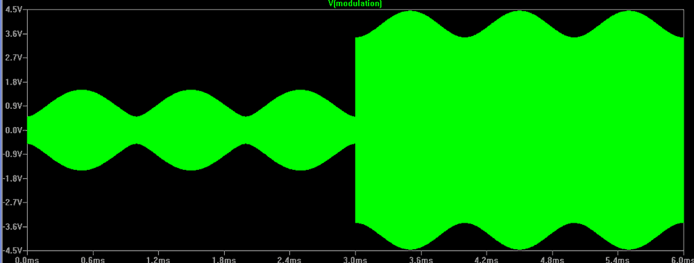
Fig. 5. Carrier is normal (1V), but only one sideband (0.5V) is present.
In Fig. 5 the carrier is normal (1V), but only one sideband (0.5V) is present. Such situation may occur during selective fading. Needless to say, audio output reduces by about 6dB, but also some distortion of the envelope appears -- the peaks of the envelope become flattened, the valleys -- sharpened. By the looks of it, distortion on the left hand side is about 15...20%. That is not as bad as in case of the carrier fading, but still audible. With the carrier exaltation (on the right), the envelope becomes visibly perfect, and, most likely, a listener would not notice any distortion.
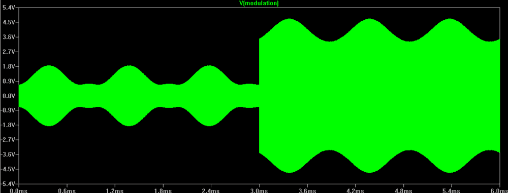
Fig. 6. Carrier is normal (1V), both sidebands (0.5V each) are present, but one sideband phase is shifted by 90 degrees.
Situation as per Fig. 6 may happen intermittently during selective fading, but more likely to be the case if the IF frequency response of the receiver is asymmetrical, or IF transformers are not properly tuned, and/or the radio is detuned, so that the carrier frequency sits on the slope of the IF passband. With such phasing defect, the AM signal has a very distorted envelope (left). However, once the carrier is exalted, the envelope becomes almost perfect, even though some minor residue of the second harmonic is noticeable. Sonic quality would not suffer, as sometimes mild second harmonic is even considered "pleasant".
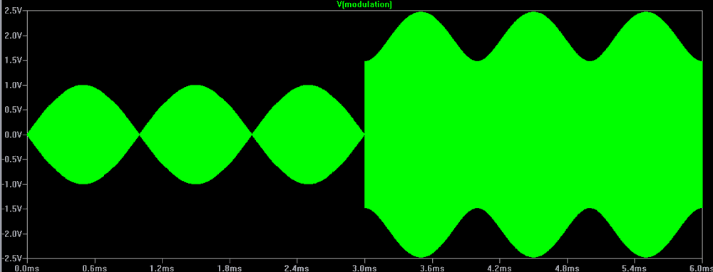
Fig. 7. Carrier is reduced by 6dB (0.5V), and only one sideband (0.5V) is present.
Fig. 7 can be considered a more severe case of selective fading, than Fig. 5. The envelope (left) gets severy distorted, but without frequency doubling "screech". With exaltation (right) the envelope resumes almost perfect shape.
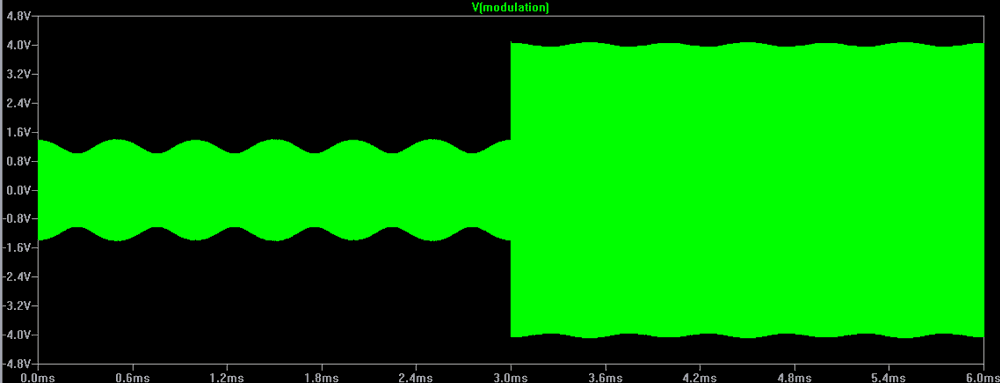
Fig. 8. Carrier and and both sidebands are of the mormal amplitudes, but the carrier phase is shifted by 90 degrees.
In this case (Fig. 8), amplitude modulation effectively becomes phase modulation. Original modulation frequency disappears from the envelope, which now contains only the second harmonic, which, without doubt, is unwanted. With the exalted carrier the original modulation did not appear, but the unwanted second harmonic reduces significantly.
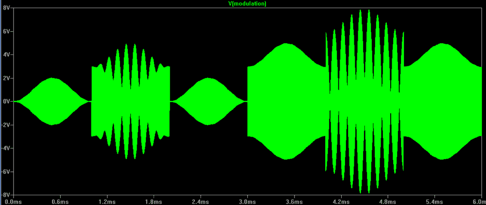
Fig. 9. 1ms long bursts of interfering signal, 10dB above the carrier, 9kHz below the carrier; other parameters of the AM signal are normal.
If an interfering burst exceeds the carrier level, it causes an abrupt "rectangular" jump in the envelope (left), which in reality is perceived as a loud "crackle". A "whistle" from the beat between the interfering signal and the carrier can also be generated. The most important is that during the burst of interference, the original modulation of the envelope disappears -- modulation gets suppressed by the interference. That behaviour makes common AM very vulnerable to impulse noise bursts. In case of the exalted carrier (right) there is no "jump" in the envelope as such, so no "crackle". The "whistle" is much louder, but there are two important differences. Firstly, the "whistle" does not suppress the modulation, but superimposed on it -- the shape of the modulation envelope is traceable through the centre line of the "whistle" ripple. In other words, the original modulation can be heard through the "whistle". Secondly, the "whistle" itself is not modulated as a "trill", but is a steady tone. Therefore, it is less annoying, and a listener's ear can easily ignore the "whistling" sound. That is particularly true if the whistle is high pitched. Therefore, carrier exaltation improves immunity to interference.
Needless to say, the scenarios shown in the above simulations, do not happen in their pure form. During real, particularly short-wave, AM listening they all come in combination of different proportion. But one thing is certain -- in any case the carrier exaltation reduces audio distortion, unwanted noise and interference, improves tolerance to IF misalignment, etc.
Carrier exaltation also allows the radio be detuned, for the purpose of widening frequency range, by capturing one full sideband while the other sideband gets partly suppressed and the carrier reduced. With a standard envelope detector such attempt would have caused a severely distorted audio, but with the carrier exaltation the sound remains clear and "crispy" because of wide audio bandwidth.
Implementation of Carrier Exaltation AM detector
The trickiest part is to create a narrow-band filter. It shall have bandwidth of about 20...40Hz, assuming that lowest modulation frequency on broadcast bands is above 50Hz. A crystal filter would be to cumbersome. Besides, its central frequency is unmovable, which would require to provide some means of automatic frequency control to the whole radio to track the inevitable frequency drift. Another limitation is that it would be impossible to shift the crystal filter to a slope of the IF passband to one sideband wholly. Fortunately and surprisingly, a filter with a tunable central frequency and a narrow bandwidth is easy to build -- it is a switched-capacitor filter.
Fig. 2 shows a simplified block diagram of a carrier exaltation detector.

Fig. 10. Block diagram of Carrier Exaltation AM detector.
Switched-capacitor filter FL1 (Fig. 10) is comprised of resistor R1 and equal capacitors C1 - C4, sequentially (cyclically) connected to R1 by a multiplexer MUX. Time constant R1C is relatively large.
If the multiplexer "runs around" at some random speed, and the input IF signal is random too, then output of the filter, Vflt-out, will be close to zero, as none of the capacitors will have time to appreciably charge. However, if the MUX cycle is syncronised with the input IF frequency, then in each period of the input signal, each of the capacitors will be repeatedly, from cycle to cycle, sampling exactly the same portion of the input sine wave. Thus each of the capacitors will slowly be charging to the average value of that portion of the sine wave. The process is somewhat similar to a stroboscopic effect. As a result, Vflt-out would assume a "staircase" approximation of the input carrier. The "staircase" is building up quite slowly, as the effective time constant is 4*R*C. The factor "4" comes from the fact that each capacitor has only 1/4 of a period to charge, in other words, R1 is effectively increased four times. Obviously, slow build-up of the "staircase" is equivalent to a very narrow-band filtering.
Before sending that "staircase" to an envelope detector, it should be smoothed by a medium-Q LC tank (L1C5 in Fig. 10). Also, as per Fig. 2, the filtered carrier shall be combined with the input signal. This is done by R2R3 network. Instead of amplifying/exalting the "staircase" before adding them together, in this case the input is attenuated by a relatively large R2, then both components are amplified by U1. Such approach ends up with same carrier exaltation. Because of relatively "sluggish" charging/discharging of the capacitors C1 - C4, the "staircase" does not get modulated, but its size is constant (unless and untill long carrier fadings take place). This is another way to visualise how the switched-capacitor filter picks up the carrier only.
Though the number of capacitors can be more than four, but four is sufficient and does not overly complicate the circuit. To get all four to sequentially connect, obviously the MUX address must be changing four times faster than the carrier frequency.
A PLL, consisting of VCO U4, frequency divider by four (MUX address generator) U5, frequency/phase comparator U6 and loop filter U7, is used to synchronise the MUX with the carrier frequency. Note that U6 is not a product detector as in a synchronous detector, but a digital phase comparator, somewhat similar to a CD4046 integrated circuit.
Operation of Carrier Exaltation detector
1. Locking onto the carrier. Suppose, at some point in time, an AM signal is applied to the input of the carrier exaltation detector (Fig. 10). As initially the VCO was running at some random frequency, and the carrier of the AM signal is not synchronised with the switched-capacitor filter FL1, output of FL1 Vflt-out is zero and not contributing. AM signal is attenuated by R2, then amplified by U1 and fed to the envelope detector U2. At this stage the whole curcuit works as a conventional AM detector, and a listener will hear the AM station "as usual". Even if the AM might not be "clean", still most of the times the output of comparator U3 follows the carrier frequency of the AM signal. That allows the frequency comparator U6, little-by-little, through the PLL filter U7, to pull the VCO closer to synchronisation with the carrier. Once VCO frequency comes very close or equal to four times the AM carrier frequency, the switched-capacitor filter is begins to build up the "staircase" Vflt-out, which grows in amplitude and provides the required carrier exaltation. At this point, a listened would notice improvement in the reception sound quality.
2. Tracking the carrier frequency drift. Needless to say, for a proper AM reception, the exalted portion of the carrier shall be in phase with the input carrier. hile the input carrier, and the VCO tracking the incoming carrier is expected to be perfect. When the radio is slowly drifting or a listener is slowly turning the tuning knob, then, first of all, the incoming AM signal will be getting out of phase with the exaltated carrier, generated from FL1 "staircase". The weighed sum of Vin and Vflt-out will also get out of phase with the VCO, to a lesser extent though. This slight phase difference will be detected by a phase comparator U6, which will, through PLL, correct the VCO frequency.
3. Unlocking and re-locking. The above tracking happens if a drift is relatively slow. If the input frequency changes abruptly, for example, a listener turned the tuning knob fast, then a relatively slow PLL will not able to track the large shift. Instead, for some time, while capacitors C1 - C4 are still keeping their charge, the filter will continue to generate the exaltation "staircase" at the same frequency. As the attenuated input component is smaller than the exalted "staircase" component, the later will swamp the former, and U3 output will be following the exaltation frequency unaffected by input having "slipped away". In other words, the PLL, locked onto itself, will keep running at the same frequency. At this time a listener would hear a whining or whistling sound, caused by the beats between the exaltation component at the former frequency and the actual signal at the new frequency.
The capacitors C1 - C4, without stroboscopic refreshing, start to gradually lose their charge, and the Vflt-out "staircase" dwindles. The rate of its decay is obviously determined by the filter time constant (or reciprocally, its bandwidth). As the Vflt-out component further decays below the level of the input signal, the whining ceases and the modulation of the input signal reappears at the audio output. The circuit resumes operation as a conventional AM detector. Now, comparator U3 begins to pick the new carrier frequency rather than the old PLL frequency. Frequency comparator U6 begins to pull the VCO towards the new carrier frequency. In other words, the process of locking onto the new carrier, as explained in paragraph 1 above, repeats.
In short, a carrier exaltation detector "naturally" and smoothly transitions from a conventional AM detection to exaltation detection and back. Unlike a synchronous detector SD-7, the carrier exaltation detector does not require special circuitry for lock/unlock detection, lock/search mode switching and audio switching from the product detector to a back-up envelope detector. Occasional "squeals" when quickly turning a dial on the radio, are not not so loud and not detrimental to the listening experience.
Carrier Exaltation detector PCB module
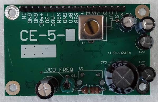
To prove the point, the author has designed several variations of the carrier exaltation AM detector modules (Fig. 11).
 |
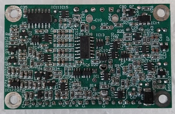 |
Fig. 11. CE-5 Carrier Exaltation AM detector PCB module -- top and bottom.
The module is designed for installation into vintage valve radios with 455kHz IF and is powered from the heater 6.3VAC. Apart from IF input and audio output, it has many additional functions and features, like AGC output, SSB mode with a product detector and BFO input, output for unlock indicator LED (the more frequency or phase mismatch is detected by U6, the brigher the LED), and an auxiliary regulated +5V output. However, this module, unlike a synchronous detector SD-7, is not going to be manufactured in quantity, so detailed connection diagram and functional description is not provided.
Compared to the SD-7 synchronous detectot, the carrier exaltation detector CE-5 has some limitations:
- can not handle deeper than --14dB carrier fading;
- can not handle stronger than +14dB (above carrier) interference.
Nevertheless, CE-5 is simpler, PCB is smaller, and connections to the radio is less complicated.
Due to the above differences, CE-5 is more suited for enhancing AM reception quality (by detuning the radio) when listening on medium waves, without fading. Also CE-5 is perfect for upgrading vintage communication receivers which have crude BFO injection into an AM detector. Installation of CE-5 would provide crispy-clean SSB reception. In comparison, SD-7 is suitable for all applications (local listening and SWL DXing) and delivers an ultimate performance in all situations.
