1. Synchronous demodulation of AM signal
Synchronous demodulation of AM signals has been known for a long time. Synchronous detector locked by means of phase locked loop (PLL) onto the carrier, greatly improves AM reception quality in the following ways:
a) Wider audio bandwidth, lower distortion, Hi-Fi, FM-like sound quality. This is possible by detuning the radio to be able to receive one sideband with full bandwidth;
b) Improved selectivity. Modulations of two adjacent stations will never be superimposed. Only one station is demodulated, and the other interfering one is reduced to high-pitched occasional "screech" or becomes completely inaudible;
c) No distortion caused by fading. On short waves, overmodulation related to selective fading of the carrier does not cause unpleasant distortion. Sound coloration changes, but clarity is preserved.
In spite of the above obvious advantages, synchronous detectors are not commonly used because of inconvenience of operation. Typically, a listener first needs to find a station in AM mode, then turn a synchronous mode on and tune close to zero beats until the PLL locks. To tune to a different station one first needs to turn the synchronous mode off, to avoid whistles, then tune and turn the synchronous mode back on. When a synchronous detector loses a carrier, annoying whistles may occur.
Synchronous detector module described in this article is specifically designed to be free from such inconvenience.
2. Overview of Synchronous Detector modules
Synchronous detector module (SD-4, SD-6, SD-7 and others) is specially designed for convenience and to fit into almost any valve superheterodyne receiver with the IF around 455kHz. It is particularly useful to enhance performance of vintage tube radios and make them enjoyable and listenable, rather than dust collecting items. It is designed to replace an original AM detector and AGC detector in the radio. Installation is easy and can be done as a part of radio restoration project.
A key feature of the module is that it is automatic -- once unlocked, it quickly, seamlessly, without clicks automatically switches to AM envelope demodulation mode and at the same trying to search for a carrier and relock onto it. Once locked again, it would switch back to synchronous mode. Thus operating and tuning a radio equipped with this module is no different to operating a conventional AM receiver.
The module includes a quality AM detector capable of handling 100% modulation, efficient integrator based AGC maintaining perfectly stable audio level regardless of the strength of a radio station. (AM detector alone is far superior to a conventional one.) For power supply it requires 6.3Vac only. It is designed to drive a magic eye tuning indicator or a small needle S-meter. And lastly, as a "free bonus" comes SSB demodulation mode.
Links for installation and performance demonstration videos are given below in the article.
Several versions of these synchronous detector modules have been designed. They are compatible in size, but slightly different in functionality. Module SD-7 which will be described below has the most extensive functionality.
The module is compact, 75 x 40 mm module (3.2mm diameter mounting holes for M3 screws are on 68 x 33 mm rectangle).

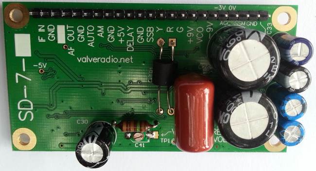
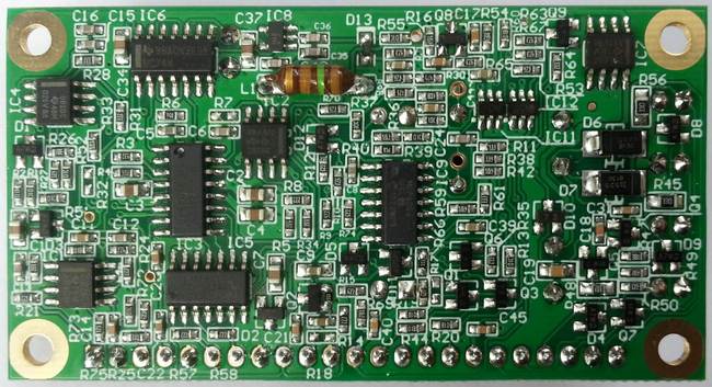

Fig. 1 a), b), c), d) Top and bottom PCB view of SD-7 module. In SD-7 the inductor can be fitted either on top or bottom side of PCB.
It is always possible to find a place for it somewhere on top, under, or on the vertical wall of a chassis of a vintage tube radio. Some examples of SD-6 or SD-4-1 installation are shown below.

Fig. 2. SD-4-1 module installed in Lafayette HE-80 communication receiver.
The example below illustrates a typical way of installation. The detector module SD-4-1 is mounted on standoffs (spacers) between the second IF and BFO cans. (SD-4-1 is an earlier model, which does not support SSB mode.) Note that most of the circuit components are located on the bottom side of the PCB. It gets sandwiched between the chassis and the top PCB copper layer (ground) which shields the module well enough to prevent leakage of harmonics from digital signals.

Fig. 3. SD-4-1 in a Mullard broadcast radio (circa 1950) -- mounted on standoffs under the chassis. (6X5GT rectifier is replaced by 1N4007 diodes shunted by yellow 0.022uF capacitors.)

Fig. 4. SD-6 mounted in Stromberg Carlson radio (circa 1943) on the vertical chassis wall under the speaker. (5Y3G rectifier valve is removed).

Fig. 4-1. SD-6 installed into Trio 9R-59D communications receiver. Original AM detector components are removed and the area is covered with aluminium foil for shielding. Original SSB product detector based on 6BE6 (V6) is still in place, but disconnected. Instead, SD-6 is used for SSB demodulation. A BFO pitch control potentiometer is fitted instead of the original variable capacitor.

Fig. 4-2. SD-6 installed into Trio 9R-59D receiver. Three indicator LEDs (red, blue and yellow) are mounted on a piece of a prototype board illuminating the S-meter from the top through its perspex bezel.
Watch a demonstration of installation and performance of SD-6 synchronous detector module in Trio 9R-59D receiver.
2. SD-7 block diagram and main features
Block diagram of SD-7 module is shown in Fig. 5.

Fig. 5. SD-7 block diagram.
Preamplifier with 12dB gain and high input impedance (2MOhm) adds sensitivity to the receiver, which particularly helps on short waves.
AM detector uses a special topology -- "magic capacitor" feedback detector -- to handle 100% modulation in the whole range of audio frequencies without slew rate (diagonal clipping) distortion. Thus audio quality in AM mode alone becomes far better than in the original radio.
PLL in SD-7 consists of a varicap controlled LC oscillator, running at four times the input IF frequency, digital phase splitter and PLL amplifier-integrator. (An earlier, now discontinued model SD-4-1 used an RC VCO based on 74HC4046.) PLL bandwidth is narrow to get stable lock, and immune to interference. SD-7 is designed for IF frequency range from 430kHz to 480kHz. Centre frequency is adjusted by trimmer capacitor C41. (In SD-4-1 centre frequency is adjusted by a multi-turn potentiometer.) VCO has a range about +/-13kHz around the centre frequency (455kHz nominal).
Lock / unlock control circuit is the heart of the system which makes the module so convenient and tuning the radio so easy and whistle-free. When PLL loses the carrier, for example as a result of a listener moving the dial quickly, the module, after certain programmable delay, goes into a search mode. At the same time audio is temporarily switched to the AM detector output. Once the PLL re-locks onto a new carrier frequency, the audio is switched back to the output of the product detector. This minimises or eliminates whistles during search and re-locking, makes radio tuning and operation convenient, whistle-free and not much different from conventional. No extra manipulations are required.
AGC (delayed) starts operating when the carrier amplitude at the AM detector input reaches 1V. This corresponds to about 250mV of IF input to the module. Because of extremely high gain of the integrator, AGC perfectly stabilises the audio output level. Hardly a 1dB change of the audio occurs while the AGC voltage spans from zero to --40V, changing gain of the radio by 80...100dB. Stable audio output ensures comfortable listening and stable PLL bandwidth. For convenience of application, the module has two AGC output options. One is from zero to --40V, the other from --3V to --40V. The later is convenient for controlling old tube line-up (6K8, 6K7, etc.) If a different initial bias voltage is required, e.g., --2V, a resistor (about 47K in this case) can be connected externally in parallel to R48 (between "AGC 0V" and "AGC --3V" pins).
SSB mode is achieved by disabling the PLL and controlling the VCO (BFO pitch) by a potentiometer (within +/- 13kHz) to optimise BFO frequency for lower or upper sideband (LSB or USB) reception. Note that since a local oscillator in a single conversion superhet usually runs higher than RF signal frequency, single side bands in the IF chain are inversed relative to the signal coming from antenna. SSB mode is a "free bonus" given by the SD-7 module.
Power supply for SD-7 is 6.3VAC from a heater winding of a power mains transformer. Internal voltages are derived by rectifiers-multipliers. Regulated +5V is available as output for convenience (load current under 10mA). In American and European radios with series heater connection it is possible to insert 10V back-to-back connected power Zeners at the grounded side of the heater string.
Signal strength indicator output of SD-7 tracks AGC voltage up to --25V of voltage with 0.5mA load capacity. It is capable to drive a "magic eye" tuning indicator or a small needle S-meter through an appropriate series resistor. This feature is extremely convenient when fitting SD-7 into a communication receiver.
Indicator LEDs can be driven from the module. Green one indicates operation of the product detector for audio output. Yellow one indicates PLL lost tracking. Red one indicates PLL is searching for a signal to lock onto. Available current is under 3mA, as the LEDs are driven from 5V logic levels through 1K resistors. It is recommended to use high brightness LEDs. Cathodes of the LEDs are grounded for convenience.
3. Pinout and pin functionality of SD-7
SD-7 module has 23 pins on 2.54mm pitch pin header. Functions of the pins are listed in Table 1.
| Pin name | Description |
| IF IN | 455kHz IF input, Input impedance 2M2||5pF, DC component shall not exceed 1 V. |
| GND | Common ground. |
| [ -3V ] | -3V DC auxiliary resistive divider output (optional) to provide fixed bias to frequency changer. See http://www.valveradio.net/radio/converter-frequency-stability.html |
| AF OUT | Audio output, decoupled by 0.1uF. Amplitude 0.8V for input AM signal with 100% modulation and above AGC threshold. |
| GND | Common ground. |
| AUTO | Mode select digital input. Pulled up internally to +5V via 22K resistor. Pulling "AUTO" low sets the module into automatic mode: switches to product detector on PLL lock, otherwise to AM detector. With "AUTO" not connected, the module remains in AM envelope detection mode. |
| AM | Mode select digital input. Pulled up internally to +5V via 22K resistor. Pulling "AM" low shuts down the VCO and forces the module to AM mode. It overrides "AUTO" control pin. |
| GND | Common ground. |
| +5V | Regulated +5V DC output. Can be used for VCO control potentiometer (BFO pitch) and/or for powering auxiliary circuitry. |
| DELAY | Analog control input. Resistor value between "DELAY' and "GND" determines delay between unlocking and search start. If left unconnected or above 220K, the delay is about 0.3...0.5s (AUTO-SLOW mode, which is recommended in fading conditions to avoid PLL jumping between close stations). Decreasing the resistor results in decreasing the delay. With "DELAY" tied to "GND" the minimum delay is 50ms (AUTO-FAST mode, which is recommended on medium waves for whistle-free tuning). Only passive pull=down resistor can be used, feeding external voltage to this pin is not permitted. |
| GND | Common ground. |
| SSB |
Mode select input. Weak pull-down (33K...220K, recommended 100K) permanently enables PLL and product detector, but inhibits search, even if PLL unlocks (SYNCHRO FORCED mode). Whistles will occur in case of fast tuning. This mode is recommended in deep fading environment and if there is no intention to touch the dial. Shorting "SSB" to ground disables PLL, activates VCO control input, and the module works as an SSB detector (SSB mode). |
| Y | Output to LED (typically yellow). High (LED is on) when PLL lock/unlock monitor detects carrier loss. "Y" sources current from +4.4V via 1K resistor. Also high in AM mode. |
| R | Output to LED (typically red). High (LED is on) if the module is searching for a carrier to relock onto. "R" sources current from +4.6V via 1K resistor. Also high in AM mode. |
| G | Output to LED (typically green). High (LED is on) if the module uses product detector for audio output, otherwise audio comes from AM detector. "G" sources current from +4.4V via 1K resistor. |
| +9V | Unregulated positive power supply output by rectification of 6.3VAC via a diode (+8.3...9V). "+9V" is provided for user convenience, e.g. to power some auxiliary user circuitry. Alternatively can be used to power SD-7 if ~6.3V is not available. |
| VCO | Analog input to control VCO frequency in SSB mode (BFO pitch). Increasing the voltage results in decreasing VCO frequency. Permissible voltage range is 0...+5V, resulting in +/-13...15kHz coverage. If open, voltage on "VCO" pin is --2.5V and VCO frequency (set by trimmer cap C41) is in the middle of the tuning range. (Input impedance of "VCO" is 23.5K.) |
| -9V | Unregulated negative power supply output by rectification of 6.3VAC via a diode (--8.3...9V). "-9V" is provided for user convenience, e.g. to power some auxiliary user circuitry. Alternatively can be used to power SD-7 if ~6.3V is not available. |
| AGC --3V | AGC voltage output starting from about --3V (weak stations) to --35...--38V (strongest stations) to the grids of remote cut-off tubes in a radio. This output is recommended for the radios with old 6A8, 6K8, 6J8, 6K7, 6SK7, etc. tube line-up requiring --3V bias for maximum gain operation. |
| AGC 0V | AGC voltage output starting from about 0V (weak stations) to --35...--38V (strongest stations) to the grids of remote cut-off tubes in a radio. This output is recommended for the radios with ECH80, ECH81, 6BE6, 6BA6, etc. where each tube has its own self-bias resistor, and AGC operates from 0V down. |
| SSM | Output to drive signal strength indicator. Voltage on "SSM" follows voltage on "AGC 0V" from 0V down to approximately --25V and then saturates while AGC can go further lower. Maximum output current draw is 0.5mA -- sufficient to drive a small needle meter via an appropriate series resistor. |
| GND | Common ground. |
| 6.3VAC | Power supply input from a heater winding of mains power transformer. Connect to ground if +/-9V DC supply is used. |
Further, table 2 summarises operation modes depending on control pins levels. Symbol (*) means "Do not care".
| Mode of demodulation | "AUTO" | "AM" | "DELAY" | "SSB" |
| AM | Open | * | * | * |
| AM | GND | GND | * | * |
| AUTO-FAST Recommended in MW band for whistle free operation while moving the dial of the radio. | GND | Open | GND | Open |
| AUTO-SLOW Recommended on crowded SW bands to avoid synchronous detector jumping back and forth between two very close fading radio stations. | GND | Open | Open or variable resistor to GND | Open |
| SYNCHRO FORCED Recommended on rare occasions on SW bands for listening to one station with no intention to touch the dial and in case of exceptionally strong interference and possibility of long deep fading. | GND | Open | * | Weak pull-down (100K) |
| SSB For listening to CW and SSB signals (on amateur bands). SD-7 does not give sideband selection/suppression above what can be achieved by setting BFO one one or the other slope of IF selectivity curve. | GND | Open | * | GND |
4. Connection of SD-7 module to a receiver
Fig. 6 illustrates a typical AM/AGC detector arrangement in a simple radio.

Fig. 6. Conventional AM/AGC detector circuit of an AM tube radio.
SD-7 synchronous detector module replaces conventional AM/AGC diode detectors, which should be dismantled. Numerous variations of connecting SD-7 are possible depending on the functionality required. For example, to implement full range of features supported by SD-7 module, the following connection diagram (Fig. 7) is suggested.
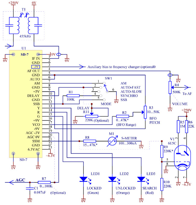
Fig. 7. SD-7 connection for full functionality.
Grounded switch SW1 is used to select operation modes, according to Table 1 and 2. This switch may be fitted in place of tone control (usually quite useless anyway) of a radio.Both a needle S-meter and a tuning indicator are shown, but only one might be actually used. Divider R9R10 is to match typical AGC range with the input range of a tuning indicator tube (A Russian octal 6E5C is shown as an example.) To limit the "BFO pitch" range, R2 can be used. Depending on the AGC range the radio is designed for and its tube line-up, either "AGC --3V" or "AGC 0V" outputs can be used. To get other initial AGC voltage, say --2V, a shunting resistor shall be connected between "AGC --3V" and "AG 0V" pins, while AGC voltage is still to be picked up from "AGC --3V" pin..
All three indicator LEDs may be used. It is recommended to install them somewhere behind the dial glass in the corner, so they do not spoil "authentic" appearance of the radio. Two examples are shown below.
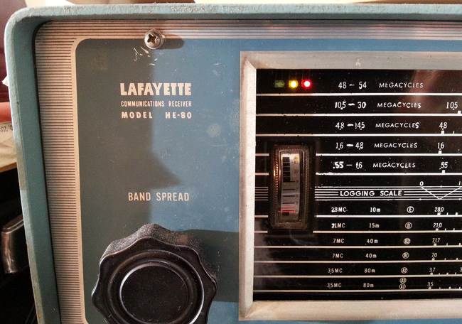
Fig. 8. Three indicator LEDs installed in HE-80 communications receiver.

Fig. 9. Three indicator LEDs installed in Stromberg Carlson broadcast radio (circa 1943).
Click on this link to watch a demonstration of Stromberg Carlson radio with SD-6 synchronous detector.
 |
 |
Fig. 9-1. Mode indication in 9R-59D. Left: AM mode -- red and orange glow of S-meter. Right: locked synchronous mode -- blue glow. AM, SYNCRO-FAST, SYNCHRO-SLOW and SSB are available in "AM", "AM-ANL", "SEND" and "SSB" positions of the FUNCTION switch respectively.
Watch a demonstration of 9R-59D with SD-6 synchronous detector.
To avoid disappointment, it is extremely important to ensure good frequency stability on short waves. SD-7 can only track frequency drift up to 300..400Hz/sec and with full carrier strength. Faster drift, especially during fading, will result in PLL unlocking and SD-7 going into search mode (if in AUTO-FAST) or backing up onto AM detector (in AUTO-SLOW) or producing a whistle (in SYNCHRO FORCED mode) . In a typical receiver AGC is applied to the frequency changer and the local oscillator frequency drifts when the AGC voltage changes during fading. To improve frequency stability, local oscillator supply shall be ripple-free and regulated, and AGC shall not be applied to the frequency changer, as described in a separate article. Instead, fixed bias to the frequency changer tube can be taken from pin 3 of SD-7 module.
On short waves, if hum seems to be louder in synchro mode than in AM mode, it most probably indicates parasitic frequency modulation of the local oscillator -- either supply voltage ripple or stray magnetic field from the mains power transformer affecting the slugs of its coils or even AC powered heater filament of the oscillator/mixer tube. Synchronous demodulation is more sensitive to phase wobble than AM demodulation. It is easy to assess frequency stability of your radio after the module is installed. Switching into SSB mode, tune into an AM station in a high SW band (13 - 19m) and listen to the beat tone. It shall be "clean" and clear, free from "sliding", "wobble", "trill" and hum. Touching and gentle tapping the chassis of the radio shall not cause excessive "jumps" and "wobbles" of this tone. If the radio is too microphonic, it might whine as a result of acoustic feedback from the speaker. In synchro mode, a radio is more susceptible to microphonics than in AM mode.
If parasitic FM is found to be present, it is important to identify its cause. If it manifests in SSB mode on high shortwave bands, then it is most likely caused by the local oscillator of the receiver. If the FM "trill" manifests on medium waves as well, then it might originate from SD-7 due to stray magnetic fields from the power transformer. In this unlikely scenario, SD-7 module should be relocated further away from the transformer, mounted on the opposite (from the transformer) side of the chassis, etc.
If both LSB (on low amateur bands) and USB (on higher amateur bands) are intended to be received with quality, R3 must be readjusted with a sideband change. If there is no room to install R3 on the front panel and it is not practical to use a double pole switch, an alternative solution shown in Fig. 10 can be used.
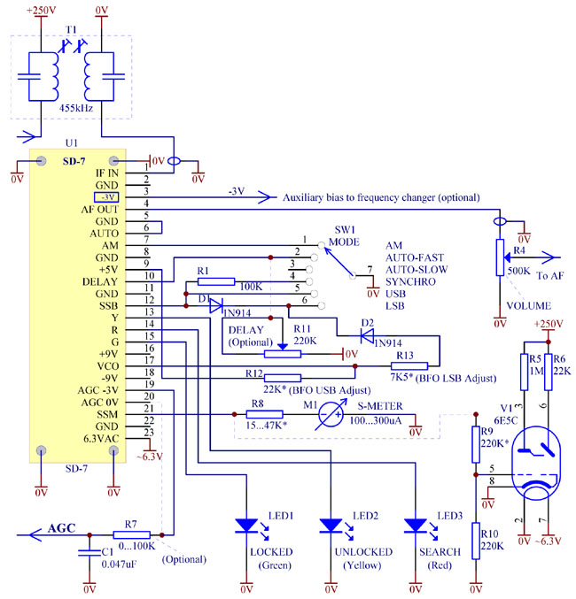
Fig. 10. Sideband selection method
In Fig. 10 the same switch controls SD-7 modes and VCO voltage by means of additional resistors R12 and R13 and two decoupling diodes. These resistors are selected to set BFO on one or the other slope of IF selectivity curve. Diode D2 may create some temperature drift, but it is negligible compared to the drift of the whole radio.
Not always it is appropriate or advisable to implement full functionality of SD-7. For medium waves local reception only, where sound quality is the primary goal, a simplified connection of SD-7 is recommended as shown in Fig. 11. AUTO-FAST mode is the best in this case and others may be left out. Only one green LED (to indicate lock) is sufficient in most cases and even it is not essential.

Fig. 11. Simplified connection of SD-7 module.
Note that since the diodes of valve V1 are not used, it becomes convenient and useful to apply cathode negative feedback over the audio amplifier to improve sound quality and reduce its intermodulation.
Strange it might sound, but high linearity of the audio amplifier is very important to achieve really good immunity to interference with SD-7. Consider the following explanation. Suppose you are listening to a station and have a very strong interfering other one nearby, say 18kHz apart. Suppose IF selectivity of your radio is not perfect, and the interfering station is leaking into the SD-7 input. Of course the interfering station will almost not audible (except perhaps for a high-pitch "screech" at times), but the product detector in SD-7 will convert it into a virtual AM station with 18kHz carrier. SD-7 in this case would work as a second mixer of your radio with a very low second IF of 18kHz. This "second low IF" is fed through the volume control to the audio amplifier. If your audio amplifier is not linear, it will demodulate this 18kHz AM radio station, and you will hear its modulation superimposed on the station you are listening. Thus a poor audio amplifier can destroy the benefit of the synchronous detector.
The mode switch can be either push-pull switch on a shaft of tone control or even a "left-click" switch (commonly used for ON/OFF function), assuming that after the click the radio enters AUTO mode and then the tone control progressively cuts highs down. So, depending on the normally open or normally closed switch arrangement, switching between AM and AUTO-FAST modes can be done by switching of "AM" with "AUTO" permanently grounded, or by switching "AUTO" with "AM" open. "DELAY" is permanently grounded for the most appropriate AUTO-FAST operation mode.
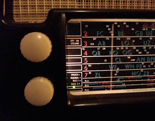
Fig. 12. Single green indicator LED in a His Master's Voice radio (circa 1950).

Fig. 13. Push-pull tone control shaft switch (bottom). Pull for AM, push for AUTO-FAST; other modes are not implemented.
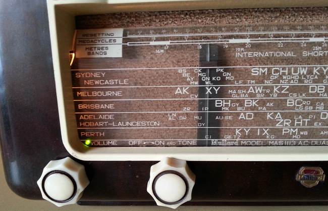
Fig. 14. Single green indicator LED in a short-wave Mullard radio (circa 1950). A three position switch in place of tone control allows for AM, AUTO-FAST and AUTO-SLOW modes. SYNCRO FORCED and SSB modes are not supported.
5. Summary of the benefits of the synchronous detector module
Installation of the synchronous detector module SD-7 gives the following advantages:
1) Greatly improved immunity to interference (selectivity). With a conventional AM detector and with poor IF selectivity of a radio, quite often two programs from two close stations are heard simultaneously, or one station sweeps over the other by sideband splatter. With the SD-7 it is not the case. Only one station is cleanly demodulated, and others interfering ones are reduced to far less invasive "monkey chatter" or pushed out of the audible spectrum altogether.
2) Clarity of sound. IF bandwidth of a cheap old radio is usually too narrow (5kHz if not less). If the radio is centrally tuned, the sound is undistorted, but muffled and too mellow: devoid of highs because the sidebands are cut down. An attempt to pick up more treble by detuning the radio results in distortion due to sideband skew and carrier suppression (on the IF slope). With synchronous detector module SD-7 it is possible to detune the radio, get the full bandwidth of one side band and at the same time have an undistorted demodulation by the product detector. AM radio sounds crisp and clear, like when listening on FM, and even better as there is no unpleasant multi-path distortion, quite common for FM reception.
3) Immunity to fading on short waves. During carrier fading the sound coloration is constantly changing but the sound is always clear, never turning into these screechy snort-like distortions at the dips of the carrier level.
4) Efficient automatic gain control. Audio level is very stable, never changes from a weak to a strong station. The radio never "blasts" when coming across a strong station. No need to always tweak volume control.
5) SSB mode. It is a free bonus since a linear product detector is already present in the circuit. It allows to listen to CW and SSB ham communications and chit-chat, which is fun and such feature invariably turns your vintage radio into a conversation point.
6) Higher sensitivity (four times higher IF gain) of the receiver which helps maintain sufficient signal level on the PLL and helps AGC operation.
6. Installation, testing and tuning of SD-7 module
A) Choose a radio of your liking of a decent size, capable of rich sound, preferably with a spacious chassis. Choose a radio with four or even five knobs, one of them to be used as a mode selector switch, as shown in Fig. 7, 10, 11. Also find a suitable place for the indicator LED(s). Use high-efficiency LED types with brightness above 100 mcd. Electrically restore the radio, replacing old capacitors and resistors, fitting three-core power cord for safety, etc.
B) Plan ahead where you would place the SD-7 module. You might need to clear some space for the module by relocating some parts, like DC choke, solder tag strips or old electrolytic capacitors which usually must be discarded anyway. Input "IF IN" pin shall be reasonably close to the IF transformer. The module shall not be too close to input RF and mixer circuitry -- to avoid possible pick-up of the module radiation around 1820kHz, though such radiation is very minor. It shall be mounted at least 10cm away from the mains transformer, choke(s), speaker magnet, relays and other sources of magnetic field to avoid permeability modulation of the VCO inductor by stray magnetic field. Steel chassis should work as a magnetic shield between the transformer and SD-7 module. Mount the module on standoffs. SD-7 comes in two variants -- with the inductor either on the bottom or top side of PCB. The former makes possible to use the shortest standoffs, the later -- better shielding. Note that even if the inductor is on the top side, its emissions around 1820 kHz are negligible, fall into disused part of shortwave band and therefore usually harmless. Grounding through metal standoffs and mounting screws is preferred as it is very reliable, lasting and has minimum impedance to chassis.
If short wave operation is intended, implement frequency stability improvements as described in a separate article. If SSB operation is intended, decide whether you are going to use a BFO pitch potentiometer or fixed switchable resistors. If reception of only one side band is sufficient (e.g., 40m ham band only), then VCO control resistors switchover will not be needed. Since audio output impedance is relatively low (3.6KOhm), shielding of the wire to the volume control is not critical.
C) Remove the original AM/AGC circuitry, connect and wire up SD-7 instead. To quickly evaluate the module, prior to permanent installation, you might at first try it loosely hooked up as shown in this demonstration video. A test jig appearing in this video is built according to Fig. 7, the magic eye tube being EM84.
D) Realign IF string. Put the SD-7 in AM mode and adjust the second IF transformer to peak because input capacitance of the SD-7 is lower than of a conventional tube detector circuit. You can tune to maximum audible noise, but it is better to use a signal generator (coupled to the antenna, local oscillator suppressed) and tune to maximum AGC voltage. The best is to use a sweep-generator and connect an oscilloscope to a test point marked "AF".
E) Set VCO centre frequency to the middle IF bandpass frequency. SD-7 comes pre-tuned to 455kHz, but actual IF of your radio may be different. This adjustment can be made in either of the following ways:
a) Temporarily switch SD-7 to SSB mode (by grounding "SSB" pin) while keeping "VCO" pin unconnected. Disconnect the antenna. Tune the radio onto a free from stations spot (recommended on the short waves). Carefully adjust C41 ("VCO CENTRE FREQ") to get the most "rich", "deep", "dense", "low", "pink" coloration of the noise sound. This will roughly correspond with the BFO being in the middle of IF passband.
b) If SSB mode is not used or not available (in case of SD-4-1 module), then tune the radio (in AM or AUTO mode) to a strong station so that it is tuned centrally -- for the most "rich", "low", "mellow" sound, or feed centre IF frequency signal from a signal generator. Set the synchronous detector module to "AUTO" mode to lock onto this station or injected signal. Carefully adjusting C41 (or a multi-turn blue potentiometer in SD-4-1) and monitoring voltage at test point TP1 ("VCO VOLTS"), aim at getting 2.5V at this point. It will be the middle of the VCO tuning range.
7. Evaluation of a synchronous detector module
SD-7 module is robust and works well even if loosely hooked up to a radio chassis. Pictures in Fig. 15 -18 illustrate SD-7 operation with the test jig. before it is finally fitted into the chassis. In the example below (with SD-6-1 module, now obsolete) a Calstan 5-valve radio chassis (6BE6 - 6N8 - 6AV6 - 6AQ5 - 6V4) was used. Test jig shown in these photos emulates Fig. 7 circuit with EM84 tube as a "magic eye" optical tuning indicator.
With such simplified test setup you can quickly get the feel of the synchronous detector.
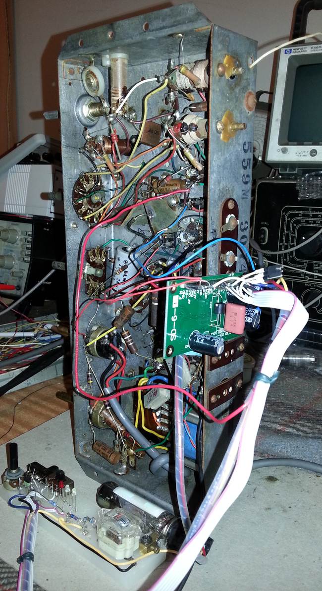
Fig. 15. SD-6-1 connected to Calstan radio chassis.
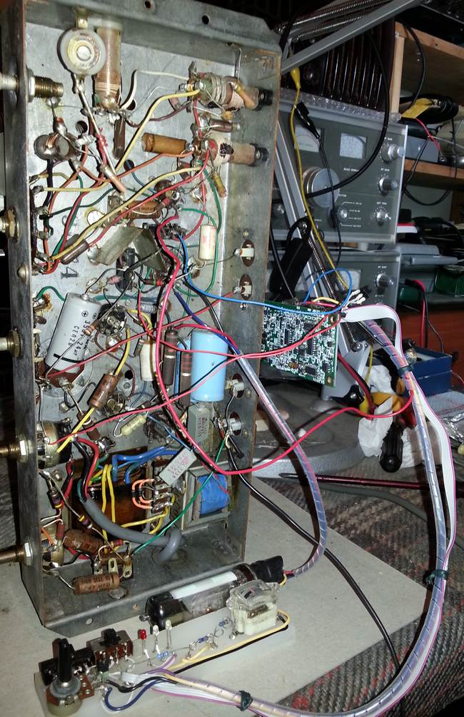
Fig. 16. EM84 magic eye and a signal strength panel meter to verify AGC operation.
In the final installation, input IF signal wire to the synchronous detector module should be as short as practical and never run under the module PCB. If this connection has to be long, a shielded cable should be used. Audio output wire usually does not need shielding due to relatively low output impedance of the module.

Fig. 17. SD-7 is locked onto a strong signal in AUTO-SLOW mode. Green LED is on.

Fig. 18. No signal (mixer tube 6AN7 removed). Both yellow (PLL unlocked) and red (searching) LEDs are on.
Upon lock, green LED is illuminated. With no signal, both yellow and red are steady on. If the radio is receiving static noise only, usually yellow and red LEDs are flashing. That means VCO is hopping around in search mode attempting to lock onto elusive random noise.
8. Installation into a radio with series heater string
SD-7 module is designed primarily to be powered from a 6.3V heater winding, but can be adapted to a radio with a series heater connection. Care must be taken not to overvoltage the module during high in-rush heater string current on cold tubes. Therefore it is recommended to insert two back-to-back series connected high power 8.2V or 9.1V Zener diodes between the heater string and common to power the module. The Zeners must be mounted on adequate heat sinks. For example, 1N5344B can be used for 150mA string and BZY93C8V2 for 300mA string. Some reduction of the heater voltage can be expected as well as possibly increasing hum due to distortion of heater voltage by the Zeners.
9. Installation into a transistor radio
Though the module is designed primarily for tube radios, SD-7 can work in a transistor receiver. The following should be considered.
a) Is there enough space inside the radio to fit SD-7 and room for mode control switch, indication LEDs and possibly delay adjustment? Are you prepared to sacrifice authenticity of your receiver and modify it? If the answers are "NO", then it is better to build a synchronous detector as a stand-alone module.
b) Power supply. If you are lucky, you may find a 6.3Vac winding on the power transformer, for instance, for the pilot dial lamps. Alternatively a small separate 6.3Vac power transformer might be used. Such are usually available from radio-hobby shops like Radio Shack, Tandy, etc. The transformer shall not be located close to the SD-7 module to avoid magnetic modulation in the VCO inductor. If AC 6.3V supply option is not possible, the module can be powered by +9Vdc and -9Vdc from LM7809 / LM7909 voltage regulators or LM7808 / LM7908 voltage regulators with silicone diodes inserted in their common legs to increase voltage from 8V to 8.6V. Pin 23 (6.3Vac) shall be grounded so that built in diodes protect SD-7 module from reverse polarity in case +9V and -9V do not come simultaneously.
Quite likely your receiver would already have +12...15V rectified unregulated DC available, so arranging +9V regulator for SD-7 will not be a problem. However, most likely a negative voltage rectifier will have to be added. If the rectifier is old fashioned full wave with a centre tapped winding, then adding a pair of 1N4004 diodes and a reservoir capacitors is trivial. If a diode bridge rectifier is used, then there are two options. One is to reconfigure the circuit into two half way rectifiers doubling the size of the reservoir capacitor to maintain low ripple. The other option is to add another negative polarity bridge rectifier, capacitively coupling it to the transformer winding (Fig. 18A).

Fig. 18A. An example of adding a negative voltage supply to a positive bridge rectifier.
c) Getting IF signal for the synchronous detector. SD-7 requires about 250mV of IF for optimum operation in terms of locking range, locking time, carrier hold, etc. Such level is readily available in a tube radio. In early transistorised receivers with the IF chain built from discrete components, like Yaesu FRG-7, Realistic DX-120, DX-150, DX-160, Eddystone EC10 and the like, such voltage is also available -- typically from the LC tank of the last IF stage. Then IF signal can simply be fed from some IF stage of the radio to the SD-7 IF input via a small capacitor, 22...100pF or through a capacitive divider (attenuator) to maintain IF input at an optimum level at strong stations with AGC working. Such coupling method works fine in, for instance, FRG-7 receiver. Some receivers may have a dedicated "IF OUT" connector, which is convenient, but if IF level is insufficient, a simple amplifier might be required.
The most difficult case is a highly integrated receiver, where all the IF chain is inside an integrated circuit, and there is nowhere to tap to the final IF stage. It might be possible, however, to tap onto a low level IF somewhere, for example, coming from a ceramic IF filter. Such trick is possible with Lowe HF-225 receiver, but the available IF signal is very low, about 500uV...1mV, so an additional preamplifier with gain 250...500 is required in front of SD-7. Design of such preamplifier is not critical, but better if it is tuned rather than aperiodic -- to minimise noise. An example of a "universal" preamp is given in Fig. 18B.

Fig. 18B. An example of an IF preamplifier for SD-7.
Due to the emitter follower Q1 it has high input impedance. Cascode topology ensures stability. By adjusting R5 and loading resistor 33K (no designator), gain can be varied over a very wide range. Thus this preamp is quite versatile and can be used practically in any situation. The same +9V supply voltage can power this preamplifier. The 455kHz LC tank from any old transistor radio can be utilised in this circuit.
d) Automatic gain control (AGC). When powered from ~6.3Vac, SD-7 generates its own AGC ranging from 0V (or -3V) down to -40V and capable of sourcing only about 20...30uA of negative current. Such AGC style is perfect for controlling the remote cut-off (vari-mu) tubes in the valve radios, but useless for the transistorised ones. Yet, it is possible to interface SD-7 to a transistor receiver circuitry.
Firstly, "AGC -3V" terminal of SD-7 should be tied to -9V rail through a 100KOhm resistor (R1 in Fig. 18C, D, E).

Fig. 18C. Automatic gain control by means of a JFET -- a "variable resistor".
This will allow SD-7, even if it is powered by +/-9V dc, to still generate AGC voltage, but in a reduced range from 0V to -8...-8.5V. Then a n-JFET can be inserted into an emitter leg of the first IF stage of a receiver. Negative AGC voltage would cause the JFET channel resistance to increase, degenerating transconductance of the IF stage and reducing the gain. If the controlling JFET is inserted literally in series with the emitter, it would provide smooth low intermodulation gain control (as JFET resistance will be creating negative feedback), but will result in the loss of maximum gain due to initial channel resistance. Alternatively the JFET can be inserted in series with the already existing emitter biasing (current setting) resistor. This way the JFET will control the DC current through the IF stage. The later method is conveniently compatible with DX-150 / DX-160 receivers RF stage. It only takes to remove the existing bipolar transistor and fit a JFET instead. Such JFET should have relatively large gate cut-off voltage, but not exceeding -7V, and low channel resistance. Ideally such AGC JFETs should be installed in more than one IF stage. Interestingly, such n-JFET AGC method can work with n-p-n transistor based circuit (common negative), as well as with p-n-p (usually Germanium) transistor based IF stages (common positive), found in very early receivers, like Eddystone EC10.
Though the n-JFET technique presented in Fig. 18C is simple and rather universal, there may be numerous alternative approaches. For example, in Fig. 18D shows how IF gain can be controlled by changing bias to the IF stages (bipolar transistor and dual-gate MOSFET are shown as examples).
Fig. 18D. Automatic gain control via common bias line with level shifting.
Usually it is easy to locate and access such AGC bias line in a receiver. Voltage range from about +3V down to 0.5V typically varies the gain from maximum to minimum. To convert SD-7 AGC range (0V...-8V) to the receiver AGC range (+3V...+0.5V) and improve load capability, a resistive divider R2R3 and an emitter follower Q1 can be used. R2 and/or R3 values can be adjusted to match the original circuit voltages.
The circuit in Fig. 18D is suitable for more common n-p-n transistor based radios. To use the same principle for a p-n-p transistor based radios, AGC voltage polarity must be inverted (Fig. 18E).

Fig. 18E. Inverting of AGC level by an operational amplifier to control Germanium p-n-p transistors.
In this circuit, AGC voltage referred to the receiver varies from about -3V (full gain) to +0.5V (complete cut-off, zero gain). Of course, scaling / level shifting resistors R3 and R4 can be adjusted for the best smooth AGC performance. Some receivers with p-n-p transistors, like Eddystone EC10, would already have negative bias on the bases of the gain stages, so for the AGC will require positive voltage. In that case the circuit in Fig. 18E can still be used, but R3 shall be either high value (10MOhm or so) or not fitted at all.
The above circuits are shown as examples. For each particular receiver, a user should understand how AGC works and design or "invent" the most suitable interface between SD-7 and the radio circuit. Combination of the above techniques can be used for different stages, e.g., IF and RF. The most important is to keep in mind that SD-7 AGC output is rather "weak" and a level shifting interface should have high input impedance. Another thing to remember is that SD-7 already has an AGC integrator, so any other long AGC time constants in the receiver AGC chain shall be disabled or bypassed.
10. SSB operation
SSB mode in SD-7 was intended as a "fun" mode -- mostly to make it possible to listen to ham radio operators on an old broadcast radio.
However, when installing SD-7 into a real communications receiver which already has a BFO and CW/SSB function, it would be impractical to remove all the existing circuitry and fit a BFO PITCH potentiometer to control SD-7 VCO. Such modification would seriously ruin authenticity of a vintage communications receiver. Fortunately, there exists a way of using SD-7 for SSB/CW reception with already existing BFO.
In most of communication receivers BFO signal is just injected into an AM detector. In similar fashion, BFO may be injected to the input of SD-7. Thus SD-7 in synchro mode will be "fooled" to lock onto this injected signal as onto an AM carrier and demodulate SSB. BFO injection level is critical. It shall not exceed AGC threshold, as otherwise AGC will shut the receiver down. On the other hand, injection shall not be too low, otherwise strong noise might knock SD-7 out of lock. Optimum level of BFO injection is about 50% of the AGC threshold. Fig. 19 illustrates the simplest method of BFO injection to the SD-7 input via a small (twisted wires gimmick) capacitor.

Fig. 19. BFO injection into SD-7 input for SSB reception
C1 coupling capacitor must be carefully adjusted. A drawback of such method is that injection level is not constant with changing BFO frequency because IF transformer T1 impedance is not constant either.
A slightly better injection level control can be achieved if injection is fed into the "cold" end of the IF tank -- virtually in series with IF signal (Fig. 20).

Fig. 20. BFO injection into the "cold" end of the IF transformer
This method works best when capacitance to ground at the input of SD-7 is low, for example when the connecting wire is short and unshielded. Otherwise ground capacitance may create a frequency dependent voltage divider.
The best is to use BFO injection with neutralisation (Fig. 21).

Fig. 21. BFO injection with neutralisation
If ratio C1/C6 is equal to ratio C7/Cin (Cin is the capacitance to ground, including shielding cable), then IF LC tank T1 virtually becomes connected into a diagonal of a balanced bridge. BFO and T1 become completely decoupled -- BFO does not develop any voltage drop on T1 and IF signal does not leak into BFO and thus can not pull of lock BFO frequency. C1 and/or C7 should be adjusted so that tuning of T1 slug does not affect BFO frequency and injection level.
Note that in all cases BFO signal is taken not from the BFO inductor L1, but from the cathode -- for better frequency stability. BFO amplitude shall be kept low if possible reducing BFO supply voltage as practical (increasing R1). BFO shall be injected at the input of SD-7, and not by a parasitic leakage into the whole IF chain of the radio.
If your receiver already has a decent SSB product detector -- balanced, diode ring or at least heptode based (as for example in 9R-59DS), then it is better not to use SD-7 for SSB function. Retain the original SSB circuitry and put SD-7 into AM mode only to employ its AGC function (and possibly S-meter function).
11. Photo gallery: synchronous detector SD-7 installed in various receivers (courtesy those radio-amateurs who provided photos)
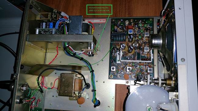
Fig. 22A. Synchronous detector SD-7 in Yeasu FRG-7. A separate 6.3VAC transformer is used for power supply.

Fig. 22B. 455kHz IF pick-up from the final IF tank of FRG-7 to the input of SD-7. Mode select switch is combined with IF bandwidth switch.

Fig. 22C. A green "synchro-lock" LED fitted to front panel of Yeasu FRG-7.
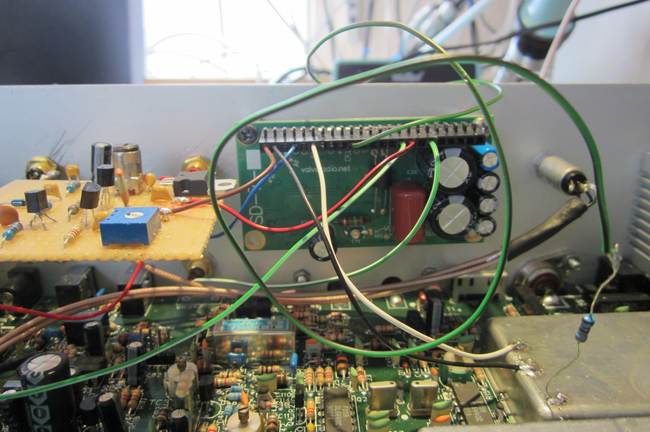
Fig. 22D. Synchronous detector SD-7 in Lowe HF-225 receiver. An additional IF preamplifier is constructed (on a prototype board) as the available IF signal to tap to in HF-225 is very low -- about 1...2mV.

Fig. 22E. Quick hook-up of the synchronous detector module SD-7 to Hammarlund HQ-129X receiver to make sure it works. SD-7 module is robust and capable of working with rather crude and messy wiring.

Fig. 22F. Final installation of SD-7 synchronous detector module into Hammarlund HQ-129X receiver. An octal socket of now redundant 6H6 AM detector tube is used for connection.

Fig. 22G. "Synchro-lock" green LED is placed behind the dial of Hammarlund HQ-129X receiver.
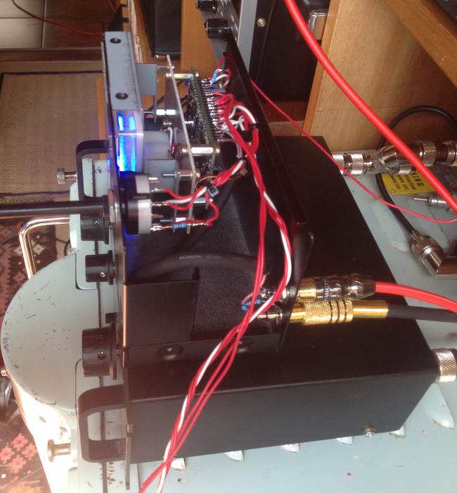
Fig. 22H. Synchronous detector SD-7 in the process of construction as an external module to work with Murphy B40 receiver. B40 has IF = 500kHz (B41: 800kHz), so a special variation of SD-7 was custom made for that application. (Another 800kHz custom modification was made for B41 receiver). Stand-alone approach is suitable for the receivers which have IF output connector.

Fig. 22I. Front view of SD-7 synchronous detector with S-meter as an external unit to Murphy B40 receiver. This way authenticity of the receiver is not compromised.

Fig. 22J. Synchronous detector SD-7 as an external rack unit (very cool!) to work with Collins R-390A receiver.

Fig. 22K. Simple installation of SD-7 into 9R-59DS. BFO (ECC85) and SSB product detector (6BE6) are left original.

Fig. 22L. Close-up view of SD-7 synchronous detector module in 9R-59DS receiver. Cooking aluminium foil is glued under the module is for shielding.

Fig. 22M. Standalone SD-7 with full mode and BFO controls built into a speaker, working together with Watkins Johnston WJ-8711 DSP receiver.


Fig. 22P. Internal wiring (left) and front panel view (right) of SD-7 with a +/-9V power supply in SP30 speaker box.

Fig. 22Q. SD-7 as an external module for AOR7030 receiver -- with the IF preamplifier, power transformer and +/-9V regulators. A copper clad grounded FR4 plate under SD-7 is an excellent idea.

Fig. 22R. SD-7 as a stand-alone module in a timber chest, complete with +/-9VDC power supply and a preamplifier, primarily intended to work with Tecsun S2000 receiver. View demo here.

Fig. 22S. SD-7 in HE-30 communications receiver. Stone-age regenerative Q-multiplier / injection BFO is ditched, SD-7 covers all modes -- AM, slow, fast synch, lock and SSB thanks to the "Selectivity" control potentiometer which is now conveniently used as BFO pitch with its switch to enable SSB mode. Three SMD LEDs -- green, yellow, red -- are mounted on a small board above the S-meter behind the dial glass.

Fig. 22T. Another example of SD-7 installed into Trio 9R-59DS receiver. "Wiring corridor" is arranged at the top side of the chassis. Note that the local oscillator (ECC85) and mixer (6BE6) tubes are removed -- because a low noise wide dynamic range solid state frequency converter is fitted for high performance and frequency stability.
Fig. 22U. SD-7 fitted to National NC-125 receiver. 6H6 detector tube is removed and SD-7 wiring is threaded through its socket (courtesy VE3GEM).
Fig. 22V. A smart and elegant solution -- instead of mounting three SD-7 mode indicator LEDs somewhere (quite often in the corner of the dial), a single tri-colour RGB LED lamp is fitted into this NC-125 receiver (courtesy VE3GEM). See a demo.

Fig. 22W. SD-7 in 9R-59 communications receiver. (A gas discharge voltage regulator is fitted, LO and mixer are replaced by solid-state circuitry for better frequency stability, wider dynamic range and less noise.) The useless regenerative Q-multiplier / injection BFO is removed, SD-7 covers all modes -- AM, slow, fast synch and SSB thanks to the "Selectivity" control potentiometer which is now conveniently used as BFO pitch with "ANL" switch now used to enable SSB mode. Three SMD LEDs -- green, yellow, red -- are mounted on a small board above the S-meter behind the dial glass.

Fig. 22 X. SD-7 as an external module for National NC-98 receiver. ~6.3Vac supply is taken from the receiver. Controls are "BFO Pitch", "Delay" and "Volume". Audio is fed to an external amplifier driving a bookshelf speaker.

Fig. 22Y. SD-4 fitted into Lafayette HE-80 communications receiver. Redundant valves 6AL5 and 6BE6 are removed. (Difference between SD-4 and SD-7 is that SD-4 uses a voltage controlled RC oscillator in the PLL, while SD-7 uses a varicap tuned LC oscillator.)
For questions, inquiries, obtaining a sample, installation advice and help use the contact page of this website.


